What's new
What's new

Saved a Hendey from the scrappers yesterday

One of the guys in our shop has been calling this lathe "the beast", but I think the plainer has earned that title, lol.

So after mulling it over awhile, I think I settled on Tory (as in Torrington, CT). I figure its like having a pet. Once its got a name, it's part of the family. I ain't name'n the little MSC lathe we got. Its gotta go! lol

Lathes seem to give off more of a female vib, I think. Its gotta be axial orientation related. Vertical mills and drills = guys.
Lathes and horizontal mills = gals.
Surface grinders.... I dunno. Eunuch or something:confused:.
 
IF it's that bad it would be best just to disassemble the bed and plane it.. Use an indicator on the planer to pick up the geometry, plane it, scrape it and then build the saddle and tailstock back up to height. I had to take off .013" to get tom's table straight again.. Sounds like yours is much worse.

I'll rig up some kind of sled soon and start documenting to be sure. Mabey I can see how bad the tailstock ways are and factor that error in when using it's base to check the saddle ways. I guess the more info I can get the better.
 
Ok, so the spindle pulley is done and mounted. It's a little out of round but I think It's normal for a split stamped steel pulley. I have some material for the motor pulley but I'm going to need to cut a crown across the OD. I'm still trying to find the missing parts for our Southbends taper attachment and this piece is a little big for it to swing. I was going to write a program to do it on the cnc lathe, but...... the Hendey (Tory) has a taper attachment too.....
:scratchchin:
So this happened last night.
1487952390917-1743091291.jpg
1487952430283-330418652.jpg
The test cut went very well. I havn't messed with the tailstock's offset yet there isn't a noticable taper in the cut. It didn't bog down when feeding in with a .100 cut (dodged the hendeyitus ?!?), the cutter just wasn't ridged enough. The toolpost is just makeshift though until I make a T nut for the CXA post.
1487953425243-1613073037.jpg
The taper attachment is back together with the exception of patching the sloted casting, and making a new ancor clamping plate.

Almost there! Still alot to do with the wiring and VFD control, but for now its being run with a drum switch.
 
Looks good :)

Have you given any thoughts to how you're going to mount a guard around the belt?

Short term, I think I'll cobble some plywood together, but long term I'm drawing up some flat model's for our sheet metal guy to lazer out of some heavy gauge sheet metal, and I'll weld it together. It's looking like the typical clam-shell style will be the most servicable. I need a tool tray for wrench's and oil cans so I might incorporate that into the front half of it as well.
 
belt.jpg
belt 2.jpg
Haven't had a lot of time to work on Tori, but have made some progress. I had another stroke of luck and found a pulley for the motor. No modification required (in fact, I even left most of the old belt dressing on it). It, like the larger pulley, is a stamped steel construction comprising of 2 halves which bolt together.

Once it was in place, I got to work making the belt out of a "sample" hide of leather (we don't really make leather goods at our shop, though we have all the tools and materials to do so). The belt was made in 2-ply fashion, 4 1/2" wide, approximately 60" diameter. The ends were scarfed down about 4" back and The whole thing was sewn together on one of our Campbell Lockstitch sewing machines. I wanted to use one our Union Lockstich machines as long straight sewing are really what they are made for, but both of the Union's in the showroom were set-up for other jobs, so the slower but just as capable Campbell got the job. IMO the Campbell does a better quality of stitch and is easier to operate anyway.

Next step: Belt Dressing! I found several old recipes online so once I get all the ingredients together I'll post what I cook-up and apply.
 

Made a video too while I had the motor temporarily connected.

Next things to address:
-Belt guard
-electrical cabinet
-control cylinder (to translate the mechanical movements of the carriage control into something the VFD understands).

That will get the lathe functional and usable. Down the road I plan to start replacing all the worn shafts, bushings, etc. I've been finding with this initial clean-up. Those'll mostly be quick evening jobs. Hopefully not TOO far down the road, I'll tear it all the way down to the ways so we can get them planed and scraped in along with the saddle and crossslide. That'll be a big task though so I want to get as much prep work done ahead of time and catch up on other projects so I can make the "real" rebuild of this lathe a quick and problem free process. I want to have all the tools, information, and of course the needed time on hand before it begins.
 
t casting 1.jpg
t casting 2.jpg
gap.jpg
Tonight's part: Finished repairing the slot casting for the taper attachment. The 2" section between brazings in the middle is the only fragment I had, and the back section I carved out of a block of Hot-roll. I roughed it out before brazing and finished milling it after it was brazed together so I could keep everything straight and parallel. Did a lot of grinding to give it the geometry that the old casting had.

All in all, it probably would have been better to replace it, but it was a good piece to experiment with and at least I have a complete pattern now. Brazing the dis-similar materials together took some heat and patience, but it stuck.

Also: you will notice that the cross slide limit rod is 1/8" off from it's hole in the cross slide. The original was probably heavily worn as the cross slide has shifted about 1/8" away from the chuck due to wear and probably some re-fitting. As I posted earlier, I'm going to try to add a wear strip on that side to bring the cross slide back were it should be when I re-scrape it later on. This should line things up better than just continually shifting it away from it's original center-line.

guard.jpg
Our sheetmetal guy is always busy... so I went ahead and started trimming out pieces for the belt guard. Still figuring out how it's going to weld together so it's removable and serviceable. I'll probably go with the standard shell-over-flat-back design. I want to put an access hole over part of the belt on the left side of the guard so I can add dressing to the inside of the belt without getting my hand sucked into it. The perforated panel will also be incorporated so I can at least show off some of the flat-belt and pulleys.control.jpg
The apron control is also back together (although I still need to replace the worn shaft). I'm working on designing a mechanism to control the VFD with. I'd like to set it up so that the spindle is off when the handle is at 'Off', and speeds up in forward or reverse the more you move it towards the corresponding sides of the dial. I think I can do it with a single potentiometer and a couple micro-switches that reverse the pot's polarity when it is moved away from the center of it's travel. I'm probably not making sense but hopefully it'll come together physically.
 
Been a long time since I've posted about ol' Tori, but I've done a little with her.

I cooked up a couple sticks of belt dressing for the flat belt. I went with a mix of Tallow, Rosin, Pine Tar, Castor Oil, Pumice Powder, and Parafin Wax, all melted and mixed together and then 'cast' in a couple paper towel tubes. The 'recipe' I derived from some notes I found in steam engine forums online. There were a lot of different mixes so I mind of went with something in the middle of them all. It worked well! Goes on easy and stays tacky.

I'm thinking about changing directions with the electrical enclosure again. The steel cabinet I was going to hang off the back of the chip pan would work, but it's not quite the right size and has a lot of space that wouldn't be useful. So I'm thinking about building a free-standing cabinet out of hardwood. I've seen similar arrangements on "high-tech" machinery from this time period so it would be period appropriate, but it would be easier to fab too which would get it off the ground faster (we have some 1" by 13" planks of Spanish oak with nothing better to do). Incorporating a ventilation fan would be easy to do.

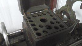
I also nabbed a pair of original Hendey collet storage boxes too. I only need one though, so if someone wants to trade some #2 collets or a draw-tube, I'm game. They're in really good shape, but are missing the mounting bracket that clamps onto the bed ways with, so that's on the fabrication radar. The 1920's patent for the arrangement has good pictures.

Pics to come when I get the tablet away from the 5 year old. I dunno what that kid sees in Ryan's Toy Review on Youtube....
 
Tori's starting to earn her keep.

The other night I took a short drop of 8" diameter pipe we had in the scrap pile and trued up the torch-cut ends. it was a very interrupted cut so the head stock gears made a lot of clatter, but it worked well.

And tonight, I just finished making a steel adapter bushing for a machine we're working on. It was a small diameter (17mm OD, 14mm ID) so my surface finish wasn't too pretty but it came out on size with very little coaxing.

I still need to get a belt guard on the machine and finish the electrical, but doing little jobs like this will give me motivation to find the time for it. I'm relearning my speed's/feeds and tool geometry to work with the low RPM. I really need to get the 4-jaw chuck pried off so I can put a smaller one on for these little jobs. I have a CXA tool post on it right now in hopes I could adjust it to use the same tool holders as our other big lathe, but It seems no matter how i set them, I have to readjust based on the job. So I'm starting to think that going back to the lantern type tool post would be easier to work with on this lathe. No big handle and the tools would fit with the shape and size of the compound better.

The wear in the way's is looking more and more fixable the more I measure and think about it. I've determined my datum points on the saddle and ways, and even though I'll need to plain down every feature on the ways, A few strips of Turkite under the saddle should put everything back where it's needed. I'm probably going to tear into the front shaft of the head stock while it's off the bed. This is the shaft that the input pulley connects to and distributes to the tumbler. It seems that a lot of the 'clatter' I hear is coming from that assembly and I can see the tumbler shimmy around while the head stock is running.
 
Another update:

I had a good chat with Hendeyman the other day about this lathe. The half-nuts were originally Babbitt apparently and someone replaced the Babbitt with bronze inserts at some point. So we determined the easiest fix would be to go back to Babbitt. When the bed get's planed, I'll have the gearbox apart and we can set the lead-screw vertically and re-poor the nuts in the cast iron holders. More on that when that time comes.

Also, I'm planning on going to the Texas 2019 scraping class at swatkins place (anyone wanting to learn how to scrape or pick Richard's brain on how to tackle your project, get signed up!) and plan to fix the saddle and cross slide there. I don't have the resources to do the ways right now, so I'm going to leave the bottom of the saddle as is and focus on fixing the cross slide ways and some other damages:

1. The cross slide screw is "floating" in it's rear mount, almost like it has 1" of back-lash. I think that the jam nuts in the back have come loose, but I may need to make some repairs to the end of the screw and the block it's captured in.

2. There's also the issue of all the gaulding and scars on the ways. I think they were cut back and refitted at some point, so I'm going to see about getting some Turkite or Rulon to push the crosslide back up to height and cover the damage. I thought about plaining it down, but if I do, I'll need to make a cast iron insert for the worst scaring on the chuck side. If I can just Epoxy some Rulon in there, I think it will make for a lot simpler repair.

3. As I posted before, I'll also need to shift the cross slide towards the chuck 1/8" to get it in the right position, so I'll cut the gib down, and make another fixed gib on the opposite side.

4. The other major repair is going to be planeing the top of the saddle down to erase some of the hammer marks on it. There's enough that I won't be able to eliminate it, but if I can lose 75% and give it some cosmetic scraping, I'll be happy. before I have it plained, I'll set it up on the mill and machine in some small repair plates where one of the T-slots is broken out.

Once all that is done, I'll get the compound and it's swivel scraped in and see if I can replace or re-scribe the dials, as they've become too light to read. I'm also going to use some J-B Weld or brazing to fill in the Arc's-of-shame. The compound took some really hard hits in it's time. I don't think it ever broke out, but someone did do some welding to fill in the worst of it. The rest is cosmetic.

I've decided to paint this lathe a dark grey as I get the different sections of it refitted. So that'll likely start after the saddle is fixed. That way I can get the primer and paint to stick while the iron is clean and dry.
 
For those of you that happen upon this, we have lifted and moved over 100 lathes, (with mobile, overhead cranes, trucks and trailers, ramps and winches, etc. up to 50ft. btw centers.) The Ctr of Gravity is usually for lathes with ctr distances about 3 X the swing diameter, and tailstock at right and carriage in the middle- usually- about ½ the swing Ø to the right of the chuck. In this case also, the motor is off. So the CG would be just over or a bit a head of the front axle, and (just speculating) this set up gave down weight on the hitch for sure.
 
20181210_191706.jpg
I've got the saddle back apart. I set it on the surface plate on 3 1-2-3 blocks, two in back and one centered in front. I used the flat areas besides the 'V' ways as an OEM flat surface, then mapped out the wear. All four flat surfaces of the cross slide are high in back and dip as you come forward. You can see the zebra stripe topography I drew out to show the transition from the high to low spots. There's a .035 difference from the lowest to the highest point, not counting the bottom of the gaulding scratches, so I'm figuring I'd need to cut .04-.05 out to get it all flat, and I'm probably going to have to cut down the top flats as well (.015 to .020) to keep the cross slide from binding against them.

I haven't mapped out the wear on the cross slide itself yet. The most intact surface is the compound mount, so I'm going to start by getting that flat and scraped in first, then use it as a reference to measure and cut the bottom surface down. I'm probably going to fly cut it on the mill, and then epoxy on some 1/16"-1/8" Rulon strips to account for the material I cut from it, and the .04-.05 I'm cutting off of the saddle ways. So the cross slide should stay at the same height, if not raise closer to the OEM height. I'm shopping for Rulon right now and have a lead on 1/16" material.

The dust cover in the middle should stay right where it is. I am going to drill some oil holes in each side of the cross slide, and over each of the bed's V-ways that will intersect new oil grooves and have a ball socket oiler on top. I'm also toying with the idea of plumbing it for a 1-shot lub system, provided I can keep all the fittings and lines out of the way. To do so, I'd need to have the cross slide oil holes come in from the bottom and drill all the holes so the fittings can be on the sides of the saddle casting. If I do that, I'll likely have 2 separate pumps, on for HD fluid going around the apron, and one for the Heavy Way lub going to the saddle.
 
20190114_182413.jpg
20190114_182334.jpg
The cross-slide is flat and parallel again. I surface ground the bottom first using the mostly original top surface as a reference, then flipped it and trued up the top surface. I lost about 1/16" of material (not counting who-knows how much was lost in wear and prior refits), but that will come back with the rulon strips. I used a torch to bake the oil out of the Arc's-of-shame and filled them in with J.B. Weld, then did a couple coats of primer, sanding between coats, to cover up the other nicks and dings in the surface. After a good coat of paint, the surface should be reasonably smooth again. I'm not trying to turn it into a show machine, but do think it practical to have less indentations so chips and oil will run off the parts better. I also think a machine that LOOKS like it's been cared for is given more respect than a "beater."

I'm working on the Gib(s) right now. I plan to surface grind 1/8" off of the old one. And for the other side, I'm either going to cut down a 1/4" thick cast iron strip, or make it out of some other material like brass, Rulon, or steel, which would be easier but won't wear the same as an iron-on-iron gib. The Rulon would wear well, AND be easy, but the price of that stuff makes me only want to use it where absolutely necessary.

I'm also getting the saddle fixtured up on a Bridgeport to repair the broken T-slot, and possibly more. Looking at the mill's travels and such, I may be able to do all my rough cutting on the mill and skip the trip through the plainer. It won't come out inherently as accurate, but I'm thinking if I tram the head in between each surface, it will get close enough for the Biax to finish.
 
I Got a really good start cutting down the saddle last night. I took .020 off the tops of the dovetails, and .045 off of the cross-slide ways. I used a fly cutter with a narrow 1/16" radius cutter (hand ground lathe grooving tool), that didn't leave the smoothest finish, but was able to reach in and under-cut the dovetails with a nice 1/8" round channel. I was able to get those 4 surfaces done in a single set-up clamped down on 3 ground blocks. Not very rigid out on the wings, but the ways cut well. I did some material removal on the 2 wings furthest from the chuck, but I'm going to need to re-clamp the work to get the other side, and I'm going to switch to a better cutter now that the dovetail is out of the way.

I still need to get my wear material ordered. I'm quoting Rulon from Bedecker Plastics in Shiner Texas (USED to be our back-yard till we moved). I quoted bigger pieces to have some on the shelf, but that stuff sure is expensive! The minimum I'd need for the crosslide would be around 4"x24".
.062"x12"x24" = $152.45 (won't work for this job)
.125"x12"x24" = $460.00
:ack2:
Granted that's a couple projects worth and it's only a small fraction of the cost of a rebuild. I just need to get it ordered. If I just order a .125"x4"x24" piece, that's around $150.

I'm also ordering some 1/8" bronze to use for the 2nd cross-slide gib. Comparatively it's a lot cheaper than Rulon (1/8"x4"x24" = $66.74), so I don't want to be a Harry-Home-Shop, but I'm considering using it under the cross-slide instead. I can also get a full sheet of Garolite phenolic (the "good" stuff that's made for ways. Wear resistant and graphite impregnated), 1/8"x18"x39" = $50.36.

My understanding is that they used to use Phenolics for way pads alot more often before Rulon/Turcite/Teflon came around, and that the plastics are much better, but the Phenolics did work. At this point, I want to get all 3 materials in hand to "play" with, but I'll use the Rulon. I'm also waiting to hear back from Devitt on a Moglice quote.

NOW, when it comes time to get the bed plained and build up the bottom of the saddle... that's going to take some work. I'm estimating I'll need 3/16" to adhere to the bottom of the saddle. That much Rulon might be out of the budget, but Moglice, Bronze, or Garolite might be doable.


Back
Top