What's new
What's new

How do I get a stepper motor to spin?

GregSY

Diamond
Joined
Jan 1, 2005
Location
Houston
I have what should be a simple task but seems to be difficult...

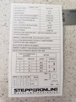
A NEMA 17 2 phase 4 wire stepper motor (12v .4amp)...all I want to do is make a 'bench test' setup that will cause the motor to spin when I turn it on. The motor is new, and I have a new DM320T driver and a pulse generator board. According to the diagrams, I have the motor and driver connected properly and the pulse generator is also powered up and should be sending a square wave pulse to the driver.

But, when I power it up with 12 v DC, the motor only locks up. When it is 'off' I can turn the shaft with my fingers but when 'on' it cannot be spun.

Am I missing a part? I've seen some youtube videos..none of which adequately address just what components you need, and how to connect them.
 

Attachments

  • stepper 1.jpg
    stepper 1.jpg
    1.1 MB · Views: 21
I've got a similar setup sitting on the bench right now. Most stepper drivers do not need anything connected to the enable pins to work; they are default enabled.

Go to the reviews on this pulse generator and there are good pictures of the connections.

Here's a good description from the first picture:
here's how to hook it up. Two options, check your stepper driver's instructions. Either connect the Pos Common to the dir+, ena+, and pul+ inputs on the driver. Then connect the dir, ena and pul outputs each to the remaining - connections (this works on mine), OR, the Neg Common to the dir- ena- and pul- on the driver and the outputs to each of the + connections.Hook up the power supply (only one ground shared between high and low inputs).The PWM option puts out a fixed frequency on the pul terminals and the pot varies it's pulse width, not used for stepper control.I'll have to disagree with one other review, the power transistor regulates the power supply, it's not connected to the pulse output.

 
Pul meaning “step” I am guessing? You need logic power to step and direction. Step should be pulse generated logic voltage/power.
Main power (12 v all amps) to vcc and ground on high voltage terminal block. Motor has b+- a+- on high voltage block.
 
Thanks everyone. I saw that controller on Amazon, too, but from the other listings it looked like the pulse generator I bought should work, too. Maybe not. The pulse generator/controller I have is very simple...it only has positive and neg DC connections and a pulse (PUL) terminal.

From what I understand (could be wrong), you need a motor, a driver, and a pulse signal to get the motor to spin. I think I have those, but it's not spinning.
 

Attachments

  • stepper motor diagram.jpg
    stepper motor diagram.jpg
    821 KB · Views: 7
You have lots of gossintas and goesouttas crosses. The power supply plus and minus go straight to ground and vcc. The motors wires only go to a -+ and b -+. The motor gets all input from driver, nothing from power supply or generator.
 
That is correct. I have the motor leads connected only to the driver, and they are connected in accordance with the color coding (per the diagram). I know the photo is not the clearest, but I do have the connections right. I just don't know if the connections are incomplete as there are 'unanswered questions' within the diagrams.

At present, I have:

Pos/Neg 12 volt DC going to the driver and the pulse generator

4 Motor leads connected to the driver per the diagram

'Pul' output from pulse generator connected to the 'pul' terminal on the driver
 
71hLdmqQa6L._SL1200_.jpg


The OUT terminal on the board should be the pulse for your driver. You'd connect that to the PUL (pulse/step) pin on the driver. You'll need to jump hot to the DIR pin otherwise the driver won't have a direction selected.

I think the OPTO pin has to be energized to power the driver as well by the manual.

1675550453838.png
 
Thanks - that's what I mean by unanswered questions....they instructions say the ENA can be left unconnected but do not say whether the DIR or Opto need to be connected. In the case of the DIR, it also doesn't say what type of signal it is looking for....a positive DC or?

I do have the OUT on the controller attached to the PUL on the driver; my statement above is incorrect. I was going from memory as to what it was called.
 
You may need a pull up or down resistor, but i hope not, those days should be gone.

Enable pin polarity is probably the problem. Many of those drives are opto isolated and they should not be burned up by a 12v pulse signal when they want 5, but read the datasheet ..
 
I've got a brace of Parker S6 drives that run just about anything. Good hardware for efforts such as this ;-)
 
Do you own an electric guitar? If you hold the pickups close to the stepper you'll be able to hear the square wave.
 
That Parker S6 looks interesting but it appears to still require a controller to make it work. My present guess is the drive I have is OK but its not getting the control signal it needs.
 
I've had similar issues Greg, and that was using a gecko. I thought "I'll just feed this thing a square wave". Dead. Hooked it up to the smooth stepper or parallel port and suddeny it jumps to life.
 
another issue - be sure the input pulse frequency is low enough. The oservable "locked rotor" implies a) pulses too fast b) incorrect pulse sequence applied c) only dc applied to windings. Best troubleshooting tool is an inexpensive scope, triggered via the input pulse train, measuring both phases of outputs. There should be a truth table for the winding states published somewhere, Check to see that correct sequence is getting to the motor leads.
 
I have no way of knowing (that I am aware of) of measuring the pulse rate. I did try turning the pots up and down to no effect. I looked at those stepper smoothers but they are $219 new - too much for what I want to spend.

These stepper motors are used in a 1995 vintage pinball machine and, generally, work well. They are driven and controlled by some fairly primitive electronics in that application....so I would hope these newer digital devices I have would work, too.

If you care, you can see the reel mechanism that these steppers drive at around 6:00-7:00 in this video

 
It spins!

After more messing around, I finally noticed the stepper motor would 'step' one notch, barely. So, I continued down that path and found the pots on the controller - which will spin in or out about 200 turns - need to be within a very tight range for the motor to run. In other words, out of 0-200 turns, you need to be between turn 75 and 77, for example. If I could measure their output I am guessing it would hit the specs of the driver.

Thanks everyone....now I can proceed with testing the motors on the bench, without depending on the remainder of the game.


Back
Top