What's new
What's new

10EE backgear mounting 3 phase motor

Karl_T

Cast Iron
Joined
Jun 13, 2008
Location
Dassel,MN,USA
This will be the third time doing a drive upgrade on the 10EE. Third times a charm :)

20 years ago, I installed a 3 phase motor and backgear using the design most everyone has done. Cut or replace the backgear shaft, install a coupling to the driving motor. This would work great but there is not enough room to do this right. The bearing on the backgear and the coupling are too close together. After only 20 years run the unit is starting to have an out of balance at high speed. No problem on a lesser lathe, but this is the 10EE -best toolroom lathe with enough ability to do larger parts too.

I'll just mention build two - 10hp 3phase and VFD no backgear.

https://www.hobby-machinist.com/threads/monarch-10ee-rebuild-10hp-vfd-no-backgear.92017/

This is a beautiful but expensive rebuild.

The subject machine already has a small vfd running. So, route 2 would be expensive and the machine would be down for weeks. I have a spare backgear from build 2. So, this project can be completed and then do a motor swap in a day.

OK, for this build I will mount the backgear just like Monarch did it - direct to the motor shaft. The problem here is finding a motor with a long shaft. I scored one - see pic. Also the backgear housing must be mounted VERY carefully. No TIR allowed.

Here's the original motor with backgear removed. I re assembled this motor to get a measurement. The shaft is 2.700" long from the plate.

original motor.jpg


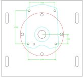
Here's a print - transfer plate is black, backgear is blue 3 phase motor ring is red.


Transfer plate.JPG

OK day one work was to carefully measure the backgear mounting and then double check it all by drilling a trial plate. I am SO GLAD I took the time to take this step - I had made a stupid transpose error that would not have been caught. This pic shows everything aligning just perfect on the backgear.


fit test.jpg
 
Last edited:
Is that a sealed motor? I don't see any fan or air openings. You might want to add an external fan to cool the motor when it is running at less than the design speed.
 
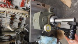
OK, got the transfer plate completed and assembled everything. Put a dial indicator on the shaft and on the backgear bore. I can easily locate the backgear BUT I did not think ahead on how to hold it in place while drilling and pinning. Got to come up with something to clamp the backgear casting while removing the motor and top plate. Then move the assembly to the mill for drill and pin.


Easter break tomorrow and have to work on the real job next week, plus another job for my son. So, thought I'd post where I'm at while this goes dormant for a bit.


Also included dimensions of bolt hole locations for the backgear. these are tested and proven. Could save some future builder a bit of time.

test fit.jpg

Capture.JPG
 
Is there a frame number or a special name/designation for that motor with a long shaft?
 
Thanks. I am in no hurrt so I will be looking for a used one a little less pricy. It is designated a 184TCZ. I know what the 184 frame size means but what does the CZ mean? Is that what designates the long shaft?
 
Had a project to do the project...
Made soft jaws and a spiral plate. Then mounted and bored them to 1.375" motor shaft size.

LATHE softjaws bored.jpg
 
Turned the motor shaft down to 1.25 and keyed it. Got the sliding backgear shift (beside motor shaft) working nice.
Now, at least for me, every job has at least one fark up. The marked hole for the motor was off 15 thou and I did not oversize the bolt bore - dumb. On first install, I stripped the threads on the motor. Got to heli coil this one before motor assembly. Then manufactue motor mounts and put it all together

motor shaft done.jpg
 
OK, now I think farked myself but good...
Being a cheap a$$, I ordered this heli coil kit from Amazon:
https://www.amazon.com/gp/product/B096TVHFPX/ref=ppx_yo_dt_b_asin_title_o00_s00?ie=UTF8&psc=1


Drilled and tapped, no problem. But their helicoil absolutely will not turn into the freshly tapped hole. tried multiple things. I have done this job several times over the years, normally no big deal. Teaches me not to cheap out, McMasters has worked every time.


OK, the tap I used was 13 TPI but oversize. No specs on the tap itself. I drilled 1/2" for this tap. So using the tap formula I remember you add the lead to the drill to get the thread diameter 1/13 + 1/2 = .077+.500 = .577 or 37/64 by 13 TPI tapped hole.
Is this the way standard heli coil works so I can buy from a better vendor??


Or am I really screwed and need to come up with some sort of custom insert? That is drill way over size to maybe 3/4x10 and then drill and tap back to 1/2x13? Better ideas could be used here.
 
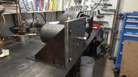
made side plates and test fit. Original DC motor in back. see pic. Just need to weld bottom to side plate, then paint. Assemble and install in lathe

side plate fit.jpg
 
ITS BREATHING!!!!!!!!!!!!!!!!!


Spent the day assembling the motor and backgear. Then putting it in place. Just like putting 2 lbs. of stuff in a 1 lb. box. Had to trim one of the feet and turn the 2" x 3/4" bolts down to 1.5". couldn't find the correct junction box, had to clobber a bit here. Powered it at 6:15 (past my quit time), of course it runs backwards, but IT RUNS. Just need to switch two wires. Got lots of cleanup to do -tighten bolts,
adjust belt tension, re-install brake resistor, adjust backgear transmission link, yada yada.


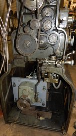
Pic of the motor moving in and in place.

10EE moving in.jpg

10EE running.jpg
 
OK, like any project, now i know how to do it better.


First, I'd rotate the motor mounts a bit CCW to get the electrical connection near the top on the motor. Got to be careful to not interfere with other holes. Did not look careful but likely 15 - 20 degrees. See green in pic.


This allows the sides of the motor mount plates mount to be right up to the motor sides. Now trim the front transfer plate to be just bigger than the motor and backgear, I'd leave it a rectangle. just easier that way. See red lines in pic.


Now drill and tap the sides of the front transfer plate for the motor mounting plate attachment. See orange hole tap points.


The motor mount plates would be a large angle iron at the base with a plate welded to reach the tapped hole on the side of the transfer plate. I'd slot both the base and the sides at the attachment points. Allows vertical and horizontal adjustment.


The unit I built is tippy forward. Had to be because one of the base plate mounts in the lathe was in the way. Extend the side plate angle iron forward of the transfer plate to solve this.


Now the motor will not fit the original mounts so you have to pull this huge base plate to and drill and tap new locations. Now that pesky rubber mount won't be in your way to slide the unit in.

side plate design 2.jpg
 
Had the lathe up to 3000 RPM yesterday... It just purrs and does the job.

Like I said in post 1, this is the best possible design to use a backgear. The running machine confirms this. Downside is finding a motor with a long shaft, needs to be 3.5" out with this design. It would be a plus to find one with a 1.25" shaft also. Not sure that's possible in 5 hp motors. I would not go smaller, 3 phase has less low end torque than DC.

Still this is a lot of labor to fabricate. My second 10EE rebuild used a 10hp motor and no backgear. Personally, I'd recommend this route unless you need to turn threads on something like 2" diameter Acme.
 
I like this solution seeing the mounting plate is one with the adapter. I had made a form fitting one to my back gear box and utilized the motor mounting feet but the belts are much larger due to where it sits now. That motor is also slick, I had to turn a whole new shaft and press the armature onto it...


Back
Top