What's new
What's new

'42 Round Dial Apron Assembly

The reason the plumbing needed doing is that it has to be routed before the Half Nuts go in, which is now going to happen.

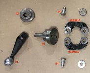
The first image is annotated, referring back to the first posting and to the Round Dial Manual. I’m doing this because there are several ways to go wrong here. Also some of the most important parts are not in this image. Not in the image are two setscrews and a taper pin.

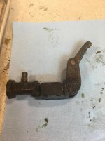
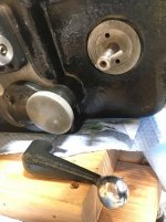
The taper pin mates the Half Nut Lever (91) to the Half Nut Cam (93) between the Half Nut Washer (92) and the casting. The fact that it is a taper pin means that while it looks like you can put the Half Nut Cam (93) into the casting either of two ways, you can’t. There is a right way and a way that will result in your disassembling all the half nut parts later when you realize that the Half Nut Lever and the Cross Feed Lever aren’t getting along.

The setscrews secure the two Half Nut Cam Pins (94) to the Half Nut Cam (93). When you’re taking this apart you remove these two setscrews, and then drive the Half Nut Cam Pins out the back of the Half Nut Cam using a pin punch through the two small holes in the forward facing face of the Half Nut Cam. When you’re putting it together, you put the Half Nut Cam Pins (94) through the bushings (98) in the Half Nut Arms (97), carefully lining up the holes for the 8-32 set screws which you then place securing the Half Nut Arms and Half Nut Pins to the Half Nut Cam. Easy Peasy yes? Actually maybe not. There are several ways the Half Nut Arms (97) can go on the Half Nut Cam, and as usual only one of these ways works. The Half Nut Arms are not symmetrical front to back, and the casting is not symmetrical left to right, nor up and down. Including the taper pin through the Half Nut Lever, that makes eight ways to put this assembly together and have it look OK to the casual observer. Only one of these ways will make you anything like happy. If the Half nut Lever faces away from all the other levers on the apron front, and you can cycle the Half Nut Cam with the Half Nut Arms attached, moving like you want them to, and not having the casting interfere with their movement, you’re there. It’s not difficult if you spend a little time looking things over. The final time I assembled these parts I greased the casting / Half Nut Cam interface and the bushings in the Half Nut Arms prior to assembly. If you’re taking it apart, don’t forget the setscrews.
half nut actuation parts 3.jpghalf nut handle.jpghalf nut lever arms.jpg
 
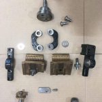
After the Half Nut Cam and related parts are in place, the next things to go on are the Half Nuts (100), the Interlocking Bar Pin (101), the Interlocking Bar (102), the Half Nut Clamp (L. H.)(99), and the Half Nut Clamp (R. H.)(130).

My Interlocking Bar Pin was too loose a fit in the lower Half Nut for my liking, and I glued it in with Locktite 638.

The first image shows the above parts plus two Half Nut Arm Bolts (96) and Half Nut Washers (92).

They go together as in the next image.

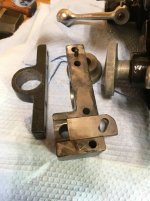
The third image shows the Interlocking Bar in the slot in the back of the R.H. Half Nut Clamp, as well as the L.H. Half Nut Clamp.

The fourth image shows the Half Nuts open. The Interlocking Bar is shown all the way to the left and disengaged from the Reverse Knob shaft.

The fifth image shows the Half Nuts closed and the Interlocking Bar has moved to the right into the slot in the Reverse Knob shaft.

Also seen is the setscrew in the Right Hand Half Nut Clamp, just to the right of the Interlocking Bar Pin in the images. Behind this setscrew is a spring and a bearing ball which fits a detent in the Reverse Knob shaft . This detent position was pretty subtle at this point with dry assembly. It became quite obvious when the apron was “filled” with oil.


I didn’t disassemble this setscrew, spring, and bearing ball. I did attempt to thoroughly clean it out from the bearing ball side with pressurized isopropyl alcohol. And then I lubed it.


half nut actuation parts 2.jpghalf nuts on.jpglock out.jpghalf nuts with lock out.jpglock out engaged.jpg
 
The oil pump is next. The first image shows my oil pump after it was partly de-gunked. You can see that the end of the bronze arm that rides on the cam is worn. This phenomenon has been well described in this forum and borrowing from the forum I silver soldered a piece of aluminum bronze into the worn groove and flied it to contour the unworn portion.

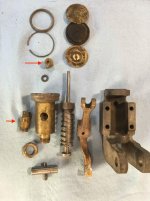
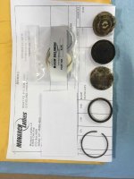
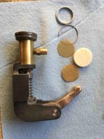
The second image is of the disassembled pump. The two red arrows point to the two parts containing ball check valves. I bought new ones from Monarch. Then I ran my old ones through an ultrasonic cleaner, followed by lots of pressure washing with isopropyl alcohol. And finally, at least in the smaller part, I could see the ball move a bit when I gently pushed on it. So as a trial, I left them in the assembled pump.

The third image is a close up of the bronze arm repair.

The fourth image shows the new filters purchased from Monarch. My old filter parts are laid out in order. This is after a lot of cleaning. When I took the pump apart these filter components were each capable of completely stopping oil flow.


The fifth image is of the pump ready to receive nice new filter elements. Note that (not for the first time) the image has a wrongly put together assembly. The bronze pump arm is in backwards.


oil pump parts filters and pump 3-2.jpgoil pump parts filters and pump 4-2.jpgoil pump arm.jpgoil pump filters.jpgoil pump parts filters and pump.jpg
 
Continuing with the oil pump. There are a lot of posts in the forum about Bijur oil pumps in Monarch lathes. I decided to run a few tests.

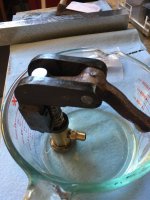
First, I assembled my pump dry. Could it pump unprimed? The forum said no, and the forum was right as far as my pump went. The setup for all tests is as seen in the first image. My pump was upright in a half inch or so of ISO 68 (shown in second image) as called for by Monarch for the apron.

Then I took the check valve off the pump barrel and squirted some oil into the interior of the pump. I didn’t fill it up immersed in oil, just squirted some in. The pump started putting oil out after a dozen pumps or so. I pumped it for a while, then tried to pump all the oil out while holding it above the measuring cup. After I thought it was empty of oil, it went back into the measuring cup and within a few pumps was pumping oil fine. Then I pumped it “dry” and left it on the bench for a month. Back in the measuring cup setup it pumped just fine.

My conclusion is don’t put your pump into your apron dry. You’ll likely be just fine if you put it in after squirting some oil into the interior of the pump and hand pumping a bit of oil through it.

And yes the bronze pump arm is on backwards in the first image.


oil pump parts filters and pump 3.jpgMobile DTE ISO 68.jpg
 
Next the oil pump gets installed. The first image shows the oil pump line which will T into the T-manifold at the end of the casting.

The second image shows the pump after the compression fitting was tightened.

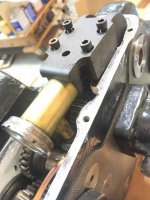
In the third image the pump is in the casting and the 1” 10-24 socket head bolts are ready to be tightened.

In the next two images the pump is in. The scale was placed to read the location of the end of the pump piston, and the images were taken at the extremes of it’s motion. I read 0.81” and 0.92” for a piston travel of 0.11”.


After the pump is in check that the reverse gear can move through it’s full travel without fouling the line. I pushed my line up a little and over to side until it was out of the way. A smart person would recall that there is some head room left where the oil reservoir will be, and route the line “down” into the reservoir.

And at last the pump bronze arm is on the right way. I used Locktite 638 on the taper pin fixing the pump arm to it's pivot pin.


oil pump line.jpgoil pump 1.jpgoil pump 2.jpgoil pump excursion 2.jpgoil pump excursion 1.jpg
 
I had a few assembly and clean up items to take care of before putting the apron through it’s on the bench paces.

The first image is of the paint mess at one end of the worm oil reservoir. I made up a tool to clean this up and to drive the worm with a cordless drill.

The second image is of the cleaned up end of the worm oil reservoir. I cleaned the reservoir up, and had before installing the oil pump vacuumed and blown out the casting.

The third image is of the rear of the apron which is all buttoned up and set up for an oil pressure test.

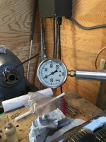
Fourth image is the front of the apron with the pressure gauge which is on the line from the T-manifold which will, with luck, later be the line to the manifold in the carriage.

And the fifth image is of the slightly overfilled (ISO 68 as before) apron. The oil lines were not primed. The pump went into the casting a few days before these images were taken. I had verified that it pumped oil as in a prior posting. Game on.


enamal cleanup pre.jpgenamal cleanup post.jpgcompleted rear.jpgcompleted front.jpgsight glass with oil overfilled.jpg
 
I was quite interested in a couple of things. First would the oil system work? And if it worked, how long would it take to see some oil and what pressures would I see?

I started turning the handwheel around 60 rpm. I saw nothing for 200 revolutions of the wheel (yes I was counting) and between 200 and 250 I noticed that oil was leaking from the junction of my pressure gauge and it’s cobbled together aluminum fitting. And while tightening that up, I saw oil at the feed tube in the reservoir. This was a happy moment, and testing continued.

The first image is self explanatory.

The second shows the first oil in the casting reservoir, and the third shows more oil.

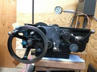
The fourth image is again self explanatory. Depending on rpms I saw up to 90 pounds per square inch on the gauge. The pump works.

I have second hand from the forum (one of Cal’s postings) that one needs 15psi at the carriage manifold for the system to “work”. Clearly that’s available, but in real life one is not frequently turning the pump cam over at 60 or more rpms. If I get that far, I’m going to do what Cal did and put an additional external oil port at each end of each side of my carriage.

oil pressure 40.jpgfirst oil.jpgfirst oil 2.jpgoil pressure 60.jpg
 
The rest of the apron checked out as far as everything working as I expected. The images attached are of oil in the Half Nut, and of a sunny end to the meat of this thread.

Oil showed up everywhere else it was wanted and places it wasn’t. I’ve put a tube of permatex on my McMaster list.


I do have some post scripts I’ll post later for any who made it this far in this thread.


oil in half nuts.jpgsight glass with oil.jpg
 
Very nice write up Karl!

What did you use to flare the ends of the tubes in the apron reservoir? They came out looking very professional.

I filled my apron worm sump with oil before putting the machine back in service. If you don't, the worm will be sliding back and forth on the feed-rod without lube. Square-dials have a shield to keep swarf out of the worm/sump. You might look at the possibility of making a sheet metal cover for yours. (I wish that I had done that, but I don't know if it's practical.)

The 15 PSI at the saddle reservoir is from Scott at Monarch and applies to square-dial machines. I have since come to find out that square-dials have a 15PSI relief valve feeding the reservoir at the top of apron, so any excess pressure is bled off. I understand that the regular metering valves have a certain amount of pressure relief built in, so perhaps round-dials took advantage of that to bleed off the excess pressure to the apron. I don't know about other machines, but mine had a regular metering valve in the apron branch. At this point in time I don't know what number metering valve was where; IIRC, they were all the same number, which doesn't make sense.

Cal
 
Thanks Cal, both for reading my thread , liking it, and for the suggestions regarding shielding the worm. I’ve seen the square dial worm guards online. Making one's a good idea.

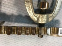
I used something that I think is called a tube flaring tool. I think I picked it up at a hardware store. It’s not a specialty item. I used the smallest aperture the tool has and needed to shim the 4mm tubing to get the tool to bite. The shim also kept the tool from marring the 4mm tubing. It works best in my hands, like all the copper stuff, if the copper has been annealed in the last 5 minutes. See the images.

Also in the images is the flow restrictor which Monarch uses on the Round Dial T-manifold. I bought the new one from them, and the numbers match the old one … both in the attached images.

Karl


tube flare 1.jpgtube flare 2.jpgT-manifold.jpgrestrictor #3.jpg
 
...
I used something that I think is called a tube flaring tool. ...

Also in the images is the flow restrictor which Monarch uses on the Round Dial T-manifold. I bought the new one from them, and the numbers match the old one … both in the attached images. ...
...
View attachment 309107
I thought that maybe you had flared the reservoir ends of the tubes in place:
309000d1609288965-42-round-dial-apron-assembly-plumbing-4.jpg


As I understand it, the metering units, like the one you used in the apron manifold, have different sizes of orifices, depending on the number. Each larger number doubles the flow of the previous number, that is, a #3 meters out twice as much oil as a #2, etc. (assuming that they're operating at the same manifold pressure). The pressure relief valve used in the square-dial will open at a certain pressure and pass as much oil as needed to maintain that pressure. I think that with a round-dial, the apron metering unit would need to be changed to get the carriage manifold pressure within the correct range, whatever that is. Maybe 15 to 30 PSI?

Cal
 
Nope. Flared first, then bedded in the casting as in the attached. The flare angle is likely standard. That and even a blind pig finds a truffle.

You are exactly correct about the metering units / pressure relief valves.

Karl

tube flare 2a.jpg
 
Post Script 1

I replaced my rack pinion with a used one purchased from Monarch. Many Round Dial / Square Dial apron parts are interchangeable, and this part is one of those.

You can see in the first two images that my original rack pinion’s teeth are worn. Also you can see small circular sections taken out of the gear teeth right at the junction of the worn / unworn portion of the teeth. These are made by the lead screw. My carriage and ways are so worn that the carriage / apron has descended to the point that the lead screw machined these circular sections out of the apron's rack pinion.

The last two images compare the old Round Dial and “new” Square Dial rack pinions.

rack pinion 2.jpgrack pinion 1.jpg
rack pinions scored and not.jpgrack pinions pointy and non.jpg
 
Last edited:
Post Script 2

All images are of thrust bearings from the Cross Feed Friction group. The smaller thrust bearing looks like it’s ball cage was hand drilled. War time fabrication I guess.

One of the larger thrust bearings was no longer adequately containing it’s bearing balls. I’m guessing the Cross Feed gets less oil as it gets less use and is higher in the casting.

The Garolite CE bearing cages were discussed in the thread.

thrust bearing old hand drilled.jpgthrust bearing rust.jpgthrust bearing new.jpgthrust bearing new 2.jpgthrust bearing new 3.jpg
 
Post Script 3


There has been discussion about the apron hand wheel clutch. As far as I can tell folks think this design works well unless it’s been “improved”. Here are some images of mine. It works really really well.

handwheel stem 2.jpghandwheel stem.jpghandwheel clutch 3.jpghandwheel clutch 2.jpghandwheel clutch 1.jpg
 
Excellent thread! I'm about to tackle much the same on a square dial machine. I'm of much the same approach on painting, it's there to protect the machine and make cleaning easier, not to appear as an auto body shop repair.

We have a lot of stickies in this forum, but I would vote for this thread as one.
 
...
You can see in the first two images that my original rack pinion’s teeth are worn. Also you can see small circular sections taken out of the gear teeth right at the junction of the worn / unworn portion of the teeth. These are made by the lead screw. My carriage and ways are so worn that the carriage / apron has descended to the point that the lead screw machined these circular sections out of the apron's rack pinion.
...

View attachment 309180
Something about that's not right. Check the following: set the leadscrew in place along the back of the apron and close the half-nuts. Jack up the headstock end of the leadscrew until it's parallel with the top of the apron casting. Check the clearance between the rack gear and the leadscrew. Then put the feed-rod and right bracket on the machine (with or without the leadscrew) and see if the feed rod is parallel to the machined flat on the underside of the ways.

Cal
 
Cal,

You’re so correct that something’s not right. But my apron isn’t going back on the carriage or the carriage on the bed for some time. My carriage is so worn that the inside flat on the bed has scoring from the carriage, like several other “wrecks” on the forum. And the initial survey of the bed ways isn’t OK by a long shot.

So … my plan is to continue with reconditioning following in the footsteps of the examples available in the forum. My plan is to scrape the bed and build up the carriage with turcite or similar a la Harry Bloom’s (beckely 23) “wreck” thread. At my snail’s pace, this promises to take a while.

Happy New Year!

Karl
 
OK, but there's no way that wear of the carriage alone should cause the leadscrew to come into contact with the pinion gear. The leadscrew and feed-rod are supported at both ends, so the they would have to bow a significant amount for that to happen. If, however, your right end bracket has been lowered as part of a quick and dirty rebuild, that might cause the leadscrew to run at enough of an angle to cause the problem. The two tests that I suggested will help sort that out.

Are the bushings for the feed-rod, in the feed worm sump, worn eccentric?

Cal
 
Cal,
I measured the gap from the top of the lead screw to the bottom flat carriage way both at the headstock and tailstock ends where there didn't seem to be wear. The tailstock end was ten thousandths lower than the headstock end. And measurements in between are consistent with that. Also I can't see any evidence of past "improvement" of the feed and lead screw bracket at the tailstock end. On the other hand, I can get a 55 thousandths thread measuring wire between the feed bushings and the feed rod. Actually between the tool I built and the bushings. But the tool is 0.750" just like the feed rod. So the bushings diameters are at least 0.805".
Maybe when I get to getting good measurements on the bed ways and carriage things will be clearer?
In any event thanks very much for your suggestions and help! I need and appreciate both!!
Karl


Back
Top