What's new
What's new

Antique lathe

JDM-oldschool

Aluminum
Joined
Jun 2, 2022
Hi all,

My name is Christoph, I am from Austria and work in automotive engineering.
I have a small workshop where I restore an 1984 Toyota Celica Supra, do some woodworking and repair stuff.

In school I loved machining on mills and lathes, I was mostly working on a huge Prvomajska lathe from the 70s. That was a great thing!
I played with the thought of buying a small new chinese lathe for a long time but somehow its not the right thing... I don´t need one, and I am more into old tools and stuff...

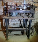
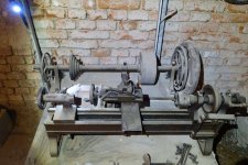
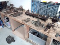
So tomorrow I will pick up that antique one. I know its not practical without a lead spindle and is really primitive but I saw it and had to have it. It´s beautiful together with the cast table.
I don´t see a possibility that I can find out who made it and if I even can get it running, but I will start cleaning it and see how far I come.

There are a few things that make me scratching my head:
Why has someone bolted it on the table backwards?
Was it originally driven with a foot pedal?
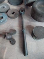
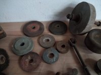
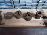
Why are there two axles with so many pulleys?

So there is the lower axle that seems to be the original one. There is also a corresponding hole in the table on the left side (under the motor) where the belt was going down.
That would have been the original setup I think, although I dont think that the V-Belt pulleys are original or if there was a leather belt before? The lathe looks somehow too old for V-belts to me.

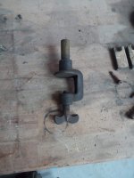
Then at some point someone has added the rear axle. The pulleys left line up with the lathe pulleys when the lathe is turned around. On the right side there is that leather belt pulley and openings in the table to feed them down to the lower axle and the lever is for engaging/disengaging the lathe with the two pulley sizes below I think. But how was it driven then? With the motor? There is no space for it, so that must have been mounted separately?
 

Attachments

  • 604_-981410910.jpg
    604_-981410910.jpg
    128.8 KB · Views: 181
  • 604_1167776574.jpg
    604_1167776574.jpg
    86.7 KB · Views: 182
  • 604_-1295654226.jpg
    604_-1295654226.jpg
    78.8 KB · Views: 151
  • 604_78702683.jpg
    604_78702683.jpg
    68 KB · Views: 138
  • 604_1092409007.jpg
    604_1092409007.jpg
    67.4 KB · Views: 174
hi christoph , i am probably not the man you need but i can see why you bought it. it looks interesting enough to keep and restore, good luck.
 
I think You have a real conglomeration, there :~)
The table especially strikes me - I think it may have originally been from an industrial sewing machine. I've never seen a lathe table with a height adjustment like that, but it's often a standard feature on commercial sewing stands, even old ones like that.
The rest of it looks like a capsule history of it's various owners inventiveness - Now it's time to do some inventing yourself .
 
Hello Cristoph

Greetings from the Catskill Mountains of New York State & welcome to our 'board. Here is my opinion about your lathe:

1. The stand or bench it is on may have been from industrial sewing machines. Industrial sewing machine stands were made with adjustable height legs and made
to be installed in continuous units if a long line of sewing machines was to be used. Industrial sewing machine stands often had a line shaft (power transmission
shaft) running down between the legs with clutches for each sewing machine.

2. The odd or "backwards" mounting arrangement may have been the result of a previous owner being unable to reverse the rotation of the motor. Or, the way the
lathe is built, it was designed for having the driving pulley mounted under the lathe. This would be typical of a foot-powered lathe. The design of the lathe may
have made mounting the drive behind the lathe impossible. This type lathe may only have been driven by a belt from a shaft located above (overhead drive)
or under the lathe (as a foot powered drive would be).

3. As the lathe is mounted, it is difficult (and somewhat unsafe) to use.

4. If you re-mount the lathe so the 'working side' is close to the edge of the bench, and re-work the drive system, you should be able to use the lathe (assuming
the working parts of the lathe are in good condition).

5. The line shaft (power transmission shaft) with the pulleys up on the bench may have been original with the lathe. The lathe may have originally been
foot treadle driven. There is a flywheel (ins deutsch: schwungrad) on the shaft, and that would have been typical of a foot-powered lathe. There are
2 cone pulleys, one on the shaft on the bench, one on the shaft under the bench. Both pulleys seem to match the cone pulley on the lathe headstock.
The type of groove in the pulleys is likely for a round leather 'sewing machine' type of belt, rather than a "V" belt.

6. My suggestion: pick the cone pulley which best matches the diameters of the pulley on the lathe, and use it to make a short 'jackshaft' or 'countershaft'.
Use the bearings that are already on the transmission shaft on the bench. You can decide if you want the drive under the lathe bench, or above it.
Some means of moving the 'jackshaft' or 'countershaft' to adjust belt tension will be needed. A modern "V" belt drive from the motor to the jack shaft
can be used, or you could use an automobile belt as is used on car engines to run the alternator, water pump, A/C compressor, etc.

A handy way to make a drive for this sort of lathe is to mount the jackshaft bearings on steel angle 'legs' bolted to the back of the bench. This puts the
jackshaft up above the lathe and somewhat behind it.
 
Thank you very much for your replies! You are great!
Sorry for answering so late, I picked it up on Friday and man that was exciting!
Most of my questions were answered when I talked to the sellers. I should have been more patient.

So where do I start? Maybe step by step... I came there to meet the sellers in a small quiet old area of the city.
They told me a bit of history. The house was built in 1927 by a retired K.u.K. Colonel. He was a maker and inventor and has built a workshop in the basement to work there together with his son in law. There was 380V 3 Phase power in the basement from the beginning, the motor that drove the lathe was still mounted on the wall and there was one of those huge knife switches with the big handle that you know from old movies beside it.
The son in law worked on it probaly until the 60s, after that it was just a heavy piece of junk in a basement that was too heavy to throw away. There were lots of cabinets in the room too but the sellers had to throw most of them away because they started to rot.

Lets go on with the table: I am very sure the table itself is original. It is massive, unlike any of the sewing machine tables here in Austria, those are mainly Singer and Pfaff and beautifully cast and fragile. The bearings of the lower axle look amazing and also far to massive for a sewing machine. When searching for those tables in german I did not find anything close at all. When searching in englisch there are similar tables but they look much more modern maybe from the 50s onward. But that was just my own search, if you have found something closer please feel free to tell me!
 

Attachments

  • 604_-269885727.jpg
    604_-269885727.jpg
    73 KB · Views: 24
The two axles:
This is where it really gets interesting: It´s not just a lathe, its a makers place!
The second axle has been added at some point to power different other things. And there are lots of different gear ratios that you can achieve for the different purposes. I will measure all the diameters and try to find out all the speeds that were possible.
This solves one of my big questions and that would have not been possible without that huge box with accessories that came with the lathe.
It has not been on the pictures so you can imagine how suprise and amazed I was when I took the things out of the box and it got better and better!

I will start with the reason for the different speeds, a grinding wheel and a surface treatment wheel. That is amazing! For sure I will never ever turn them on because it looks so unsafe but I am really happy to see the puzzle pieces coming together.

They are mounted on wooden plates that are made to be put on the lathe bed, after I have reassembled the table I will try to see where but I think the grinding wheel should fit the right large pulleys and the surface treatment spindle the pulleys of the lathe.
 

Attachments

  • IMG_20220604_074319.jpg
    IMG_20220604_074319.jpg
    636.2 KB · Views: 22
  • IMG_20220604_074250.jpg
    IMG_20220604_074250.jpg
    679 KB · Views: 22
  • IMG_20220604_074245.jpg
    IMG_20220604_074245.jpg
    449.8 KB · Views: 22
But wait, there is more...

I won´t write too much and just add the pictures, there came so much cool stuff with it and that I did not know about it makes it even more amazing to me!
And the best thing: Everything is working! The axles, the spinde, everything moves. A bit hard but not like it is seized, just a little bit sticky from the old grease. All the bolts and nuts i tried yet opened as if they were new.
 

Attachments

  • IMG_20220604_074332.jpg
    IMG_20220604_074332.jpg
    565.7 KB · Views: 26
  • IMG_20220604_074325.jpg
    IMG_20220604_074325.jpg
    609.7 KB · Views: 22
  • IMG_20220604_074233.jpg
    IMG_20220604_074233.jpg
    819.9 KB · Views: 21
  • IMG_20220604_074225.jpg
    IMG_20220604_074225.jpg
    618.7 KB · Views: 21
  • IMG_20220604_074201.jpg
    IMG_20220604_074201.jpg
    731 KB · Views: 23
  • IMG_20220604_074141.jpg
    IMG_20220604_074141.jpg
    794.3 KB · Views: 20
  • IMG_20220604_074128.jpg
    IMG_20220604_074128.jpg
    621.2 KB · Views: 22
  • IMG_20220604_074118.jpg
    IMG_20220604_074118.jpg
    652.3 KB · Views: 24
  • IMG_20220604_074113.jpg
    IMG_20220604_074113.jpg
    769.7 KB · Views: 25
  • IMG_20220604_074018.jpg
    IMG_20220604_074018.jpg
    846.4 KB · Views: 27
Look at this :eek:
The tobacco can is even brand new and unopened!
 

Attachments

  • IMG_20220604_074519.jpg
    IMG_20220604_074519.jpg
    633.5 KB · Views: 14
  • IMG_20220604_074503.jpg
    IMG_20220604_074503.jpg
    551.9 KB · Views: 13
  • IMG_20220604_074438.jpg
    IMG_20220604_074438.jpg
    640 KB · Views: 13
  • IMG_20220604_074425.jpg
    IMG_20220604_074425.jpg
    496.4 KB · Views: 14
  • IMG_20220604_074351.jpg
    IMG_20220604_074351.jpg
    623.2 KB · Views: 14
well, that's quite a haul!

I'm happy its found a good home, and I think someone over there in your region would have a better idea of just what you have. personally, I would do a lot of research first, and I would avoid aggressive methods such as acids and abrasives as much as possible.

have you found any makers marks or other information on the castings? also, a careful look at the style of the castings, such things as the bearing blocks, spokes, original paint or other coating, and any markings will help to identify what is original to the machine.

cheers and good luck with it!
 
Yes I am really interested to keep it original!
I am reading a lot about the local machine factories back then, but most of them are long gone.
I will contact the technical museum in Vienna, they might be able to help me.
There are holes for a plaque on the machine bed but the plaque is gone.
There are a few hints that might help... The color is the same dark red on all cast parts so I think it is the original color and by checking lots of pictures it seems to be quite uniqe and rare.
Also the turn wheels look rare to me, most of the machines of that era seem to have cross handles instead.

I also have the names of the original owners and try to get a patent check done in my company.

For cleaning i will try a few things but maybe stick with Petroleum (kerosene) and reuse the old can.
 
OK - This has been driving me crazy - I was sure the stand was from an industrial sewing machine.
You can't compare the delicate cast iron legs from domestic machines, to what was used in sewing factories around the turn of the 20th century - apples and oranges.
The first photo is from a sewing industry museum in Bielefeld, which was the home of Durkopp, Adler, Phoenix, and other sewing machine brands.
The second photo is of the legs from a Singer 7 Class machine, a huge machine that weighs in around 200 lbs - You can see that they very much resemble your table legs.
Bielefeld Museum.jpgSinger 7 legs.JPG
 
Thanks a lot for the information and the pictures! Those legs look really close to mine, i could not find anything remotely similar!
Then it makes sense, there were probably more sewing machines than lathes around and by jugding how everything else is put together they used what was available.
 
There is some progress :)
I cleaned the table and the bed, there was a lot of dirt but no rust at all on the rails. It just needed some WD40 and very fine steel wool.
I also disassembled the tailstock, there is also no rust, but the spindle has seen a lot abuse. Someone bored out the mt1 taper and there is a step inside now. It is too small to go to mt2, so there will not be another option than to get that done new.

The chuck that I took apart looks great! just a little old grime to be removed, some new grease and it will be fine.
 

Attachments

  • IMG_20220607_160011.jpg
    IMG_20220607_160011.jpg
    621.6 KB · Views: 25
  • IMG_20220607_161408.jpg
    IMG_20220607_161408.jpg
    506.8 KB · Views: 26
  • IMG_20220607_165107.jpg
    IMG_20220607_165107.jpg
    683.6 KB · Views: 26
  • IMG_20220607_165713.jpg
    IMG_20220607_165713.jpg
    619.1 KB · Views: 26
You might see about getting a new tail stock ram made, with a good taper - You'll find the lathe a lot more usefull if the tail stock is functional. Or possibly there is some work around for the damaged taper - Maybe boring the ram, and pressing in a MT sleeve?
 
You might be able to salvage the old tailstock quill by shortening it a bit so that you can ream a good taper in the end. Even if it limits the quills travel, it could get you going enough that you could make a new quill on the same lathe.
 
From my rough measurements the bore is around 15.5mm in the front and way more than 13mm in the ground. I don't have the right measurement tools yet, so the ground i could just check by sticking a 13mm drill in.

So it is right between mk1 and mk2. The two rusty adapters show the same. Mk1 is falling in and mk2 is too big at all.

The outer diameter is 20mm, so there is not enough material to get it to mk2. And with all the deep marks and scratches around it is not hardened i guess.

Someone also tried to ram the mk1 adapter in the wrong direction. There are marks on the what i think is a B16 Side of the Adapter and the ram is slightly widened in the front.

I think i have two options after buying the right measuring Tools.
First is to turn my own Adapter from this to mk1 and use that to get exact enough to make my own new quill, hoping that the lathe can handle some good steel.
The second is maybe better but much more boring, make a drawing and get it done somewhere else. I could get it done in my old school for cheap i think.
 
2. The odd or "backwards" mounting arrangement may have been the result of a previous owner being unable to reverse the rotation of the motor. Or, the way the
lathe is built, it was designed for having the driving pulley mounted under the lathe. This would be typical of a foot-powered lathe. The design of the lathe may
have made mounting the drive behind the lathe impossible. This type lathe may only have been driven by a belt from a shaft located above (overhead drive)
or under the lathe (as a foot powered drive would be).


I was once told that the German immigrant machinists who worked in the Detroit auto factories would work on what we would call the back side of the lathe; with the tool cutting in the down position. Maybe this lathe was used in that manner. Just a convention.
 
My thoughts on the backwards mounting. There is only 1 bolt at each end holding the lathe to table, if you reversed the lathe from where it was found the step pulleys would be closer to alignment (hard to tell until its done), my guess is it was done for storage purposes so the knobs would not get bumped or snag clothing in a cramped basement used for storage.
 
Sorry for not adressing this question before!I asked the sellers when I picked it up.

The two bolts are fixed with wing nuts so it was easy to take off.
When they had to move it away from its place they took it off to make the whole thing a little bit lighter to carry and didn't put it Back on in the correct orientation. I could have mentioned that earlier.

But intersting information that they used lathes backwards too, i guess the whole cross sled would have to be reworked, what was the benefit?


Back
Top