What's new
What's new

Antique lathe

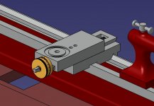
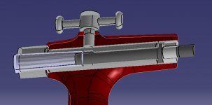
Yesterday i have been in the workshop again and started with measuring everything that I have cleaned so far in detail.
Especially the parts that need attention, the Quill and the spindles.
To see more closely what options I have I started Cad modelling the parts. I think I will have to keep the TR11 spindle diameter and make a complete new spindle if I dont want to mess around with the bearing diameters and the nut.
The 1 on the right is 8,3mm, just a bit smaller than the TR11 center diameter, a TR10 will mean I have to put a bushing on, but I dont see a way to hold the bushing in place, and the bearing diameter would be close to 7mm, thats a bit tiny...
The 2 on the left is exactly the 11mm as the thread. I would have to bore the sled larger to fit a TR12.
Also the whole spindle is about 3mm from the upper sled. With a larger thread there wont be a lot material left on the brass nut.

I think i might try to make it myself after the lathe is running and if I can improve a bit the backlash it has now. Some material does not cost a fortune and a cheap tap and die set should work long enough for two or three threads. Or?
Like that one: cheap set
 

Attachments

  • 5.jpg
    5.jpg
    106.6 KB · Views: 10
Making a new spindle would also give me the advantage to make it longer to incorporate a micrometer collar in future.
 

Attachments

  • 6.jpg
    6.jpg
    176.5 KB · Views: 2
I also have an idea for the quill.

I measured the tapered section and it is 14,6mm in the front, 13,6mm in the rear. 29mm long. The rear measurement was at around 26mm due to the measuring tool diameter.
If i calculated it correctly it is around 2,2 deg, similar to a morse cone.
After the 29mm there is a step down to the spindle diameter.
To get to an MT1 there would have to be an around 1,5mm thick sleeve. Thats a bit thin.
I think the best is first to make a tip that fits that taper and later to make a new quill with the threaded part from the old one as an insert brazed in.
 
JDM:

You are correct in your thinking as to making a new tailstock quill. Machining the old quill to save the threaded portion is something I was going to suggest.

If you do not want to braze (and put heat into the new quill), here is an approach that has been used on similar repairs:

1. Machine the old quill to save the threaded portion.

2, Turn the threaded portion so that it has a 'collar' or 'flange' at the end where the tailstock screw would enter it. This flange will transmit the thrust from the screw into
the quill.

3. Turn the body of the threaded portion so it can be shrink fitted into a reamed (or bored) hole in your new quill. The shrinkage allowance is very small, perhaps
0.0002"-0.0005". You may find that turning the threaded portion's body to slightly larger diameter and polishing to size with emery cloth (schleifpapier ?) will
get you where you need to be. Heating the quill to about 250-300 degrees F and putting the threaded bushing in the freezer will get enough size difference
to allow the parts to fit together. Once the temperature returns to normal room temperature, things will be locked tight together.

4. Another idea is to machine things as I've noted, very close fit on the body of the threaded portion into the reamed (or bored) hole in the new quill. Instead of
a shrink fit, use Loctite 603. I speak from experience with Loctite 603 (cylindrical parts setting compound). It is green, thin bodied, and WORKS. On one occasion,
I needed to make an extended drill bit. I machined the shank of a bit down in the lathe and made the extension with a reamed fit to take the turned down shank.
I did not care to go up to my garage to use the oxyacetylene torch & silver brazing, so used the Loctite 603. In about 20 minutes, I was drilling holes with that
extended drill bit.

If you think about how the forces act on a tailstock quill and tailstock screw, you will see that the heavier force is a thrust load pushing the quill towards the headstock.
A flange or collar on the nut will transmit this force rather than relying on a connection between the body of the nut and the quill. The connection between the body
of the nut and the quill only serves to keep the nut from rotating within the quill. On larger lathe tailstock quills, I have seen this type repair done using small
socket head screwed to hold the flange on the nut into the body of the quill. These screws were located so their heads were half on the flange of the nut, half
on the end face of the quill. Your lathe is too small for this type repair.
 
Your ideas are great and I try to implement them to make my life easier!

I just ran into another issue. The quill as it is is too small for a MT1 taper.
First the diameter. The 11mm spindle is almost the size of the larger 12mm diameter of the taper.
Second the length. The quill is 102mm long, the spindle 76mm, gives 26mm free length for the taper plus a few mm to push it out.
The MK1 cone is 62mm long, so either the cone would stick out 30mm or i cant use the rear 30mm of the thread which would give me a travel of less than 40mm. Both is not practical.

I think the quill is designed to hold a short B-Type cone similar to those used for drill chucks.
The marks on the quill from the 4 jaw chuck are not because the quill has been reworked but because someone made a tip for it and used it to hold the tip true in the lathe.

So the quill has to be longer. Either with an MT1 and figuring out how the spindle size will affect the taper or with a diameter increase of the quill itself and fitting an MT2 with little wall thickness in one area...
 

Attachments

  • 7.jpg
    7.jpg
    104.6 KB · Views: 2
JDM:

I am happy you appreciate my posts. Regarding your lathe's tailstock quill: as I read your post, my mind flashed to the thought there is an even smaller Morse Taper, the 'number 0'. I checked my "Machinery's Handbook" to be sure I was not mistaken in my thinking. The number 0 Morse taper is 0.252 inches at the small end (approximately 6,412 mm), 2 inches 'plug length' (approx 50,9 mm) and 0.3561" diameter at the mouth of the quill (åpprox 9,06 mm).
The taper in inches per foot = 0. 6246

You discussion of the tailstock quill on your lathe has another possibility: the lathe maker may have used a 'special' or 'proprietary' taper rather than a standardized taper. From your previous posts, you had noted the tailstock quill had been bored to some larger, straight diameter. Any idea as to what the original taper might have been has been lost as a result.

I think it is unlikely that a drill chuck taper would have been used in the tailstock quill. Drill chuck tapers are generally a shorter taper and a bit steeper than the type of taper used in lathe spindles and tailstocks. The tapers used in lathe spindles and tailstocks use a very small taper so as to be 'self locking'.

On a small lathe such as yours, back in the days when such lathes were often foot-powered, the torque (Drehmoment ?) was quite low. This low torque would not have been large enough to require a heavy taper in the tailstock to hold drills. A small diameter tailstock taper would have worked OK.

I've never seen a Morse number 0 taper, but it does exist. Using a standardized taper such as the Morse number 0, you can use a Morse taper reamer to finish the taper in the new quill. Whether you can find Morse number 0 taper centers or arbors for drill chucks is a whole other matter. My own belief is that if I can produce the internal taper with a reamer, the hardest part of the job is done for me. Making male tapers for centers and arbors on the lathe can be done easily. The finished internal taper is used as a gauge to check how accurately the male tapers are turned.

With the measurements of the tailstock quill you posted, even the Morse Number 0 taper seems too large. This means the lathe builder used a special or non-standard taper of their own design.

Here is another idea: look up 'standard taper pin' data in a machine design handbook (or get it on-line, I am a dinosaur, so I still think in terms of using reference books). Possibly a large standard taper pin will work for your tailstock taper. Using a large standard taper pin reamer, you can then produce the internal taper in the new quill and have a taper that fits and is self-locking. The standard taper pins used in the USA may be a bit too small, but the British Standard Taper Pins offer a wider range of diameters. Both British and US taper pins use a taper of 1/4" per foot.
 
I think the number 0 is too small, the issue even with the number 1 is that the 11mm spindle is larger than the taper.

But by thinking all this through I came to the conclusion that the taper in the quill is the original one and it was just a dimension that the company chose before it was standardized. And you are right, due to the small torque it probably had it did not need to be larger.

I think the marks on the quill are not there because someone has reworked the quill. I think someone made a new center by first making the taper that it fits the quill and then made the tip using the quill as a holder in the four jaw chuck.
I would also use that technique to make a new intermediate solution.

I made a fast drawing. It looks as if it could work. Maybe I should even keep it that way and just make a tip and an adapter for a B12 drill chuck.
 

Attachments

  • 8.jpg
    8.jpg
    94.2 KB · Views: 2
You mentioned the torque, that reminded me of another open topic.
The gearing. I figured that out too. I use one of the old pictures where its not taken apart to show it.

The motor drives the No 1 bottom right.

The lathe can be driven off the lower axle by No 4 (higher speeds) or the hidden No 5 (lower speeds).
No 2 and 3 drive the upper axle, 2 consists of a fixed and a loose wheel that acts as a clutch for the belt.

3 phase motors back then had 1400RPM.
Based on the diameters the lower speeds would be from around 120 to 530 RPM and the higher speeds from around 320 to 1350 RPM.

That is quite fast for plain bearings isn´t it?
 

Attachments

  • 9.jpg
    9.jpg
    587.9 KB · Views: 17
Today I have been at the workshop again and continued the work.

The cross sled is finished. It looks good and despite the worn upper spindle I was able to adjust the nut so tight that it has only about 5 degree backlash and it still moves easily.
The lower nut also fits well but I need to get shims for the spindle. It has about 0,4mm play.
All in all I am satisfied. I think for the beginning I can live with it.
The sleds fit well although there is a huge damage on the upper sled as you can see on the picture.
DSCF5074.jpg

Next was the headstock. It is a really interesting system.
DSCF5078.jpg
Both bearings are tapered, so even with some wear it can always be adjusted to run without play.
The bearing surfaces look smooth with no grooves and just some color changes (high temps).
The spindle is not hardened, it is really soft. I had to file the thread in the rear where the axial bearing runs to get the locking nut back on.

Now I unerstand how the spindle works. But what is the correct process to adjust it.
DSCF5092.jpg

The rear bearing sleeve has some cracks in the key area. It might cause troubles in future i fear.
DSCF5090.jpg

The spindle has the same taper inside as the tailstock, so I really have to make custom centers.
Oh and it has a center bore. Just above 9mm... Its tiny but at least something I guess...
DSCF5095.jpg

And in the first spindle picture you can see that I broke one of the oilers. Which is quite bad because as everything else on the machine it has a M6,5 thread with a strange pitch so I will not find a replacement. I guess now its time to learn brazing. Or getting an adjustable oiler and put an M6 Helicoil insert in.
 
Hi all,

My name is Christoph, I am from Austria and work in automotive engineering.
I have a small workshop where I restore an 1984 Toyota Celica Supra, do some woodworking and repair stuff.

In school I loved machining on mills and lathes, I was mostly working on a huge Prvomajska lathe from the 70s. That was a great thing!
I played with the thought of buying a small new chinese lathe for a long time but somehow its not the right thing... I don´t need one, and I am more into old tools and stuff...

So tomorrow I will pick up that antique one. I know its not practical without a lead spindle and is really primitive but I saw it and had to have it. It´s beautiful together with the cast table.
I don´t see a possibility that I can find out who made it and if I even can get it running, but I will start cleaning it and see how far I come.

There are a few things that make me scratching my head:
Why has someone bolted it on the table backwards?
Was it originally driven with a foot pedal?
Why are there two axles with so many pulleys?

So there is the lower axle that seems to be the original one. There is also a corresponding hole in the table on the left side (under the motor) where the belt was going down.
That would have been the original setup I think, although I dont think that the V-Belt pulleys are original or if there was a leather belt before? The lathe looks somehow too old for V-belts to me.

Then at some point someone has added the rear axle. The pulleys left line up with the lathe pulleys when the lathe is turned around. On the right side there is that leather belt pulley and openings in the table to feed them down to the lower axle and the lever is for engaging/disengaging the lathe with the two pulley sizes below I think. But how was it driven then? With the motor? There is no space for it, so that must have been mounted separately?
How would it line up if the lathe was turned 180* on the table and the hold down bolts put in there? looks like that may be what is wrong.
 
Last edited:
Thank you for your answers! You are right.
It was put on backwards after the sellers took it off to carry the heavy table away from its original place.
 
I received the new motor yesterday. It´s a 750W sewing machine motor which I will mount under the table (I will drive the lathe directly and not use the large axles.
It has a rpm range from 100 to 4500. With the right pulley I will get a roughly 4:1 gearing with the largest pulley on the lathe.

I think that should work fine and is sufficient for the small size.
 

Attachments

  • 614bsm8-KwL._SL1001_.jpg
    614bsm8-KwL._SL1001_.jpg
    78.9 KB · Views: 3
A friend sent me a link to an unrelated video on this channel.
I took a look to see what other videos he may have .
I was surprised to find this one and thought you might like to compare some of the features on yours lathe with those shown starting here.
I noticed this other one too and there are several more about his lathe restoration .
Perhaps if you contact him through his You Tube page you can compare notes and maybe he will have seen a lathe that is a closer match to yours on his travels.
I noticed in the video in the second link he shows a couple of Erlich lathes and a catalogue with some in it.
There are several threads on this forum by people looking for information about similar machines and Tony has some info on the Erlich machines on his site.
Jim
 
I continued a bit in the workshop yesterday. Unfortunately my time there is a bit limited at the moment so the progress is a lot slower than it could be.
I am a bit further with the age. I found the letters DRP and a 1xxx number on the chuck (of course I did not take a photo of the number and I forgot it, but its a 1000 something). It turned out DRP is Deutsches Reichspatent, that means the number is the patent number. All numbers below 3411 have been issued in 1877 and the patent was valid for 15 years.
So at least the chuck is from between 1877 and 1892 and maybe the patent number will also help me to find the manufacturer.

So what did I do in the workshop?
I cleaned and reassembled the headstock spindle. Adjusting it was far easier than I thought.
IMG_20220716_113146.jpg
I measured the spindle and it is 0,06mm off. Given the age of the machine and that it has seen heavy use I am really happy with it!
IMG_20220716_113204.jpg
IMG_20220716_113236.jpg

I then cleaned the largest chuck that came with it. It´s 85mm in diameter. It turned out really good and with new grease it works like new.
IMG_20220716_115958.jpg

I used a milling bit which is the most accurate straigt and round thing that I found for measuring it. It shows that the chuck is out 0,25mm. The chuck itself has some play on the adapter, I could not move it more to the center. Next time I will try to turn it and bolt it in another orientation to the adapter, maybe it gets better. The adapter itself is 0,06 out just as the spindle.
IMG_20220716_122909.jpg
IMG_20220716_122926.jpg

I also started to mount the motor controller. I wanted to give the belt clutch lever a use again. So I connected it to the potentiometer to turn the motor on and regulate the speed. It works like a charm, I am really happy how it turned out!
IMG_20220716_132557.jpg

So thats it for now!
IMG_20220716_132934.jpg
 
No EARLIER than.. is all that reliably tells you.

Expired patent numbers often survive on latter-day goods assembled long after they have expired.

Keeping in mind that the Austro-Hungarian Empire was already old and well-established as a technological powerhouse, but "Germany" was still a collection of Independent "stadts" until 1871, that's about as old as it could get under their registration!

As to 'whom' check sources for JAWS. MANY makers of the chucks they HAD fit have vanished but still get mentioned.

Then you hunt for them by name in the history of the water mills, factory buildings, birth, marriages, deaths of the founders in the villages where they had once flourished.

People.. and their enterprises ... were "news" in earlier times. Before it became mostly sensationalism, violence, and political circus.

Three of America's earliest makers of lathe chucks? Were to become related by marriage!

Europe? Near Mutters, I had the privilege of a chat with the Widow of the founder of a prominent hotel chain. She said that her family - and that of her husband - had each been innkeepers... for four hundred years.

Interesting challenge ahead, Detective Brenner!

You are totally right, it could still be younger. But anyway it is just the patent of the chuck. And this is the largest and most "modern" looking chuck of all that came with the lathe. In principle the lathe itself can still be older.

I think the second from left might be the original one. Maybe after cleaning that I can find some more information:
IMG_20220604_074113.jpg
 
I also found a solution for the Lathe key. All that you can buy today are too big. But I found out that the square of a thread tap fits perfectly.
So I ordered a cheap set of 2, will cut and braze it into a socket, that should work well:

IMG_20220716_133737.jpg
 
Give that a re-think.
A key should be weaker than the chuck part it mates to.
I reach into my extensive stash of US and Metric keyway stock, instead.

IF/AS/WHEN failure is induced?
The cheaply replaceable part should "fail safe", first. Not the hard to replace part.

One THAT small can be file-formed off round rod in a few minutes, torch heat-treated about as fast. No welding required.

Very good point! I thought a softer square that wears might do more damage than one that stays in shape.

It´s about 5,3mm so a 6mm key could be modified to fit.


Back
Top