What's new
What's new

Bearing Issue...Never Seen This Before...

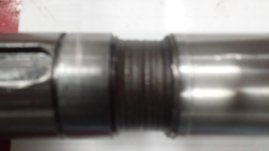
Without actually having this thing in my hand, I am as sure as can be the finish pattern is chatter and severe chatter at that. It's bad enough that the size will vary through the bore and be the actual size will be difficult to determine. If the shop that made this was ok with this severe chatter, it's not much of a stretch to say they'd be ok with missing the tolerance.

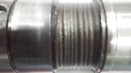
Dont overthink this and look for the least obvious solution! The bearing spinning in the housing didn't make that pattern. If someone is saying it did they are totally full of crap! Ask them how the bearing made the chatter in the groove.

Lastly there is simply no way the installed fit was .002 press and now it is .003 clearance!
 
That's not from a bearing, but out of curiosity what kind of bearing goes in there? I presume a cup/cone if you were shooting for a .002 interference? Either way with the thin wall, a .002 interference probably isn't real once installed as the housing likely swells.
It's funny you brought up the housing being thin walled. I have been pushing to get these things redesigned adding a grease connection, making the walls thicker, and add wiper seals. I even offered to do it for them, but got told bearing specialists designed these and they paid good money for the design. I asked how bearing specialists could miss the fact that these are grease-able bearings, with a grease groove and holes and not add a grease fitting to the outside of the housing.

Edit: Not having them in front of me right now, but the walls only measure about 0.125" thick.
 
This was on the non-drive side.
If this is the non-drive side, is there a reason this bearing is not floating in the housing?

With your drive being fixed and now having your non-drive side also fixed, where is your expansion going?

I suspect the bearing failed because it locked up. Unless this is a low speed application and no growth to be expected.
 
What do you mean here?

He means that the interference fit holds better with a shrink fit than if the parts are pressed together cold. Pressing an interference fit smears the material and high points from both parts get knocked down. Heating the external part and assembling with no force, then letting the heated part cool in place keeps those high points intact to help hold better.
 
What do you mean here?
EDIT:
Easa associations literature states it was something like 8 times better hold”

The jist of what they where saying was when you push a sleeve or bearing in you smooth/flatted the hills and vallys on one or both parts (depending on hardness differences.

But if you use heat or cold to alter the fits diameters so they slip over each other and then the temp normalizes and the correct interference is made up. But the hills and vallys where not smoothed during install. Now that they are mating with pressure the hills/vallys bite into each other creating what can be described as a micro locking surface interface.
 
Not to hijack but this is related and since the responders have correctly diagnosed the cause, I will post the strangest bearing failure I have encountered(in over 50yr's experience)
This is from a 1 year old ,just out of warranty.$ 3+ mil high end machine.
20221202_070310.jpg
The first is the ball bearing inner race and the others are the shaft.
This is a short two bearing shaft that has a small cam on the end , tooth belt drive on the other. Both bearings are good as far as the balls and races. The drive end housing and shaft are within specs.
 

Attachments

  • 20221202_065958.jpg
    20221202_065958.jpg
    476.6 KB · Views: 36
  • 20221202_070018.jpg
    20221202_070018.jpg
    625.8 KB · Views: 36
Last edited:
Not to hijack but this is related and since the responders have correctly diagnosed the cause, I will post the strangest bearing failure I have encountered(in over 50yr's experience)
This is from a 1 year old ,just out of warranty.$ 3+ mil high end machine.
View attachment 397274
The first is the ball bearing inner race and the others are the shaft.
This is a short two bearing shaft that has a small cam on the end , tooth belt drive on the other. Both bearings are good as far as the balls and races. The drive end housing and shaft are within specs.
I've been to two county fairs and a goat roping contest and ain't never seen no crap like that!
 
We have this bearing that failed at my place of work. As you can see, it kind of looks like fluting, but this is the outer housing for the bearing to sit in, not the bearing race, which is where I would expect to see fluting. When it was put in, the bearing had a .002" interference fit and now it measures +.003". The bearing that came out, rotated freely and smoothly by hand. This housing was installed three days before this as a brand new install before it got pulled for an unrelated issue. I am just wondering if anyone has seen this and if so, what caused this wear in this area? Thank you in advance.
That looks like a lot of the thin-wall lathe work I have been forced into in my shop efforts, although that chatter is worse than I usually end up with. That part must have been annoyingly loud while being bored "to size", which apparently didn't give anyone a clue about what was happening and what the net result would be,,,,
 
Not to hijack but this is related and since the responders have correctly diagnosed the cause, I will post the strangest bearing failure I have encountered(in over 50yr's experience)
This is from a 1 year old ,just out of warranty.$ 3+ mil high end machine.
View attachment 397274
The first is the ball bearing inner race and the others are the shaft.
This is a short two bearing shaft that has a small cam on the end , tooth belt drive on the other. Both bearings are good as far as the balls and races. The drive end housing and shaft are within specs.

There’s more to that story for sure.

To the op, your situation is pretty obvious, poor machining, no qc control and ignorant/incompetent assemblers resulting in failure, luckily caught early. Compounding all of this is poor engineerinv imo, although I don’t know exactly what the application is here, still looks weak.

If you want to give me the actual bearing part number I can tell you what to hit for housing tolerances.
Thanks but I'v got all the specks. I just made a new shaft rather then buildup. I keep a lot of tight tolerance metric TG&P rod stock just for small shafts like that.
The shaft looks just like the start of a weld build up and is probably harder than the race , like I said don't understand it. The cam is not a severely loaded item, uses a Delrin cam follower, and is tight on the shaft. Must have something to do with the cyclic motion of the cam. Don't know the shaft material but I'm sure the bearing is 52100. The shaft is about18" long and the other end bearing goes into the machine frame measures 1-1.5 thou clearance.
I thought I'd seen and repaired every possible type of worn shaft and bearing known to mankind!

There is one other possibility , someone may have welded up the shaft and those ridges are hard welds under what ever the final over lay was. No signs of heat though and the only other person that might have done that retired a year or so ago.
 
I would complete tear down. Balance rotor. get bearing shoulder to shoulder dimensions. Bearing widths(starting with DE). Check housing depth for such bearing width( is DE locked?) Very generally speaking. DE is locked( throw common sense clearance for growth) and after all measurements should(again very general) have around .080-.130 "slop" for the ODE. Vibration is a frequency, I would guess that something is out of balance, alignment, or housing bores arn't correct for your bearings(check journals also). Does this happen with no load? If it does you may try going with an insulated bearing or an insulated sleeve on ODE. If you use insulated your bore specs will open up quite a bit because of the difference in heat transfer.
 
Not to hijack but this is related and since the responders have correctly diagnosed the cause, I will post the strangest bearing failure I have encountered(in over 50yr's experience)
This is from a 1 year old ,just out of warranty.$ 3+ mil high end machine.
View attachment 397274
The first is the ball bearing inner race and the others are the shaft.
This is a short two bearing shaft that has a small cam on the end , tooth belt drive on the other. Both bearings are good as far as the balls and races. The drive end housing and shaft are within specs.
I had someone bring in an identical looking shaft recently. On close inspection it looked like the inner race or shaft had worn down slightly the shaft had then rotated in the bearing and abraded the shaft down about 6mm undersized. The customer asked me to weld it up and re-machine the shaft. I politely declined.
 
That looks like a lot of the thin-wall lathe work I have been forced into in my shop efforts, although that chatter is worse than I usually end up with. That part must have been annoyingly loud while being bored "to size", which apparently didn't give anyone a clue about what was happening and what the net result would be,,,,
You should meet these guys at that shop. They once did a roller on one of our machines that was .075" out from bearing to bearing at 8' from center to center. That roller was exiting to see in the machine and vibration analysis was going off like a Christmas tree at 50 RPM. I honestly have been trying to get my company to stop using them, but they always come back with it's cheap and they do emergency turn arounds quite quickly. I always say back, "Is it really cheaper when we have to send the thing back three or more times for them to get it right?"
 
There’s more to that story for sure.

To the op, your situation is pretty obvious, poor machining, no qc control and ignorant/incompetent assemblers resulting in failure, luckily caught early. Compounding all of this is poor engineerinv imo, although I don’t know exactly what the application is here, still looks weak.

If you want to give me the actual bearing part number I can tell you what to hit for housing tolerances.
I would appreciate the second check on both the housing and shaft. I did the math for the fitment when I started noticing that we were replacing these bearings every four weeks and no-one here could give me a good answer on if it was a K5, K6, H6, H7, etc. type fit. The part number for the bearing we are using is SKF BS2-2206-2RS/VT143.

P.S. You are spot on with poor engineering practices and incompetent installers all around, hence I am leaving at the end of June. Long story, but I find it hard to work at a place where torque wrenches are never used, micrometers for bearing replacement gather dust, and the answer to something failing is to just swap in a completely different piece of gear.

Sorry to everyone for posting, I should have caught that chatter mark going all the way to the bottom of the bore and the chatter on the outer edge of the c-clip groove. I brain-farted. LOL. There is an old dude rolling in his grave right now, because he would have slapped me upside the head saying "I taught you better than that."
 
  • Like
Reactions: Ox


Back
Top