Bakafish
Hot Rolled
- Joined
- Feb 21, 2022
- Location
- Tokyo Japan
I've collected quite a range of the Big Daishawa BaseMaster height setters. There is very little information out there on what they look like inside, or how serviceable they are. Here in Japan, these are treated pretty much as disposable as they basically charge as much to 'service' one of these as they cost new from a discount supplier.
They are well built, and there is very little that can go wrong, but I see broken ones advertised all the time and picked up some of the cheaper ones so I could tear them down and answer my curiosity. I thought I should try and document this in hopes of it being helpful to someone or at least be interesting how they chose to achieve their purpose.
These units have been recently updated, I suspect the new models only added additional LED's to improve visibility and are internally unchanged, but do not know this as a fact.
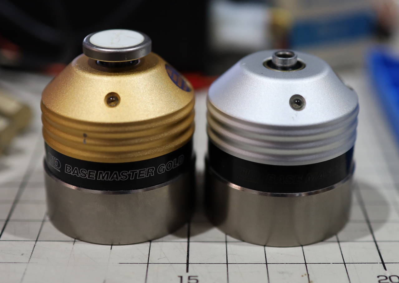
The difference between these two is that the base model uses a continuity circuit that requires a conductive path from the base through your machine and tooling to complete the path when coming into contact with the top plunger. The Gold version uses a more sophisticated system that has a kinematic structure internally, and only requires a minimal force on the plunger to break that contact. So no conductive path is required with the Gold version, which may be important if your machine is insulated or uses non-conductive tooling.
I will note that a vast majority of the Gold units I see for sale have experienced damage to the ceramic contact disk inset in the top of the plunger. It is not a user serviceable part, and seems pretty sensitive to crashing, so be aware of this before choosing one of these. BIG Daishawa does not offer a replacement part here, so you are forced to exchange the entire unit at a very high cost. Hopefully this post will help those who have experienced damage to institute their own repair rather than junk an otherwise functional little unit. I will document my own attempts at refurbishing these units at a later date.
Also, due to the aggressive downsampling of this forum all the images are deep linked. If they don't appear for you I apologize, complain to the forum for being so resource restrictive at the time of this posting. Okay, on to the teardown.
The BaseMaster BM-50 has a single rubber plug directly opposite the LED on the top housing. Removing that exposes a 1.5mm hex socket set screw. I assumed this was the height adjusting screw (both of these units are shipped from the factory at 50mm to within a micron) but it is actually the plunge depth adjustment screw.
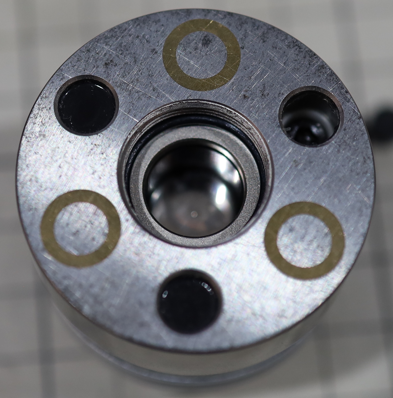
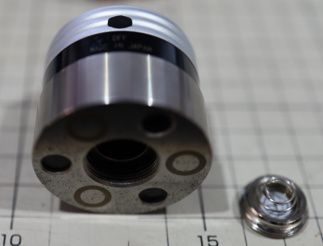
The bottom shows three embedded magnets and three potted holes. These are actually rubber plugs with a very thin layer of black sealant. Removing these plugs exposes three M4 cap head screws. Removing these screws allows the base to detach.
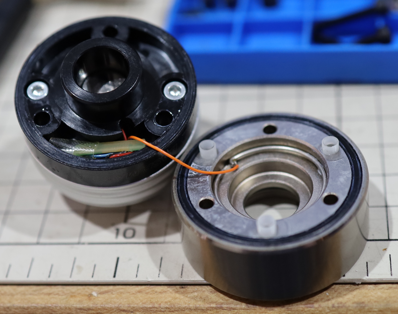
It is connected electrically to the middle housing by a wire soldered to a spring loaded ring that is press fit into a recess in the bottom block. This is easily removed with a sharp object. There is an o-ring to seal it (all these sections are similarly sealed) and there are plastic insulators to prevent the 3 screws from shorting between the sections.
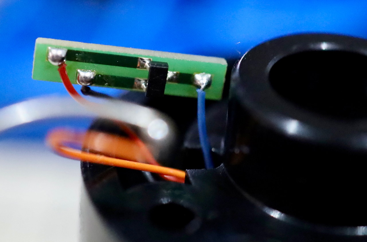
Inside the middle housing there is a tiny 'circuit board' with a single surface mount component. I believe it is a transistor, my camera just wasn't up to the task of capturing the markings, I will try to document this better when I repair and modify these.
Two more cap head screws fasten the middle and upper housings, removing them exposes the plunger. There is a spring that is captured between these two housings and is what helps with both the conductive path and the backpressure of the plunger compression. No plunger depression is required on this unit to trigger the LED, it is a purely conductive trigger.
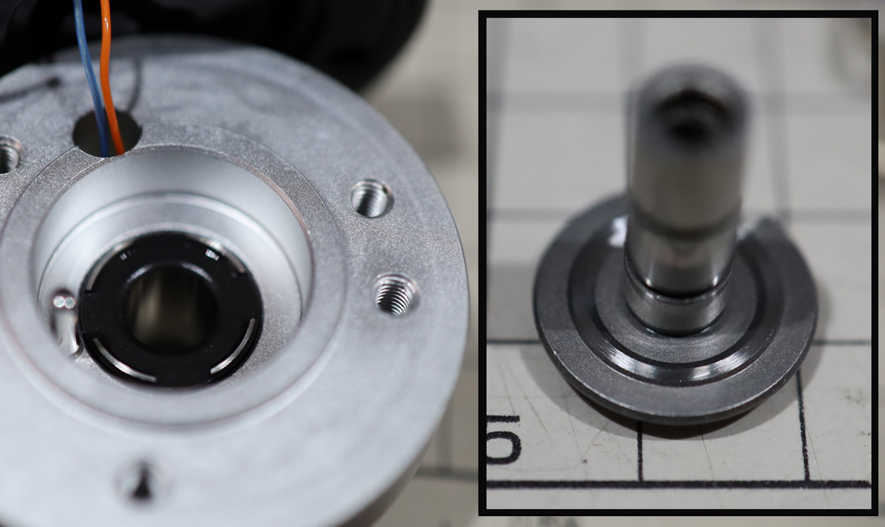
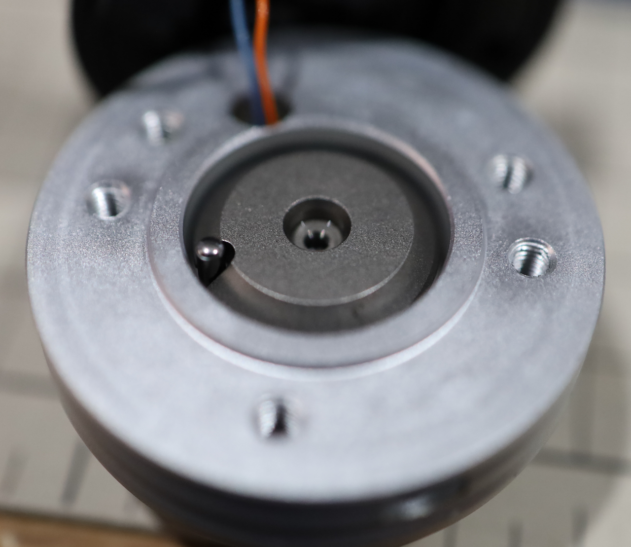
The plunger is rotationally locked by a pin that fits in a slot in the plunger, and has what appears to be a precision machined set of surfaces to ensure it always returns to the same height after being depressed. This consists of a conical area turned on the shaft that seats in a matching ring, divided into four segments. I don't have enough knowledge of Kinematics to explain the logic of this segmented arrangement, but I'd imagine there is an interesting reason for it to be broken up like this.
The plunger is threaded axially with a standard M4 thread that the (missing in this patient) disk shaped upper tool contact surface screws in to. I speculate that the height is dialed in at the factory by using the travel adjustment screw on the side to lock the plunger in place, then it is directly ground to height. I base this on a lack of any Loctite residue on the threads and the uniform grinding marks on a new example of this model. It is quite possible that they set the height just using thread friction and careful manufacturing though. I mention this in case you have a crashed unit with some damage to this contact surface, unscrewing it a few turns with some Loctite and regrinding it with the plunger locked in place may return it to the fray.
Okay, our next subject is the Gold version. Right off the bat I can see a circuit board through the (2xSR44) battery compartment. There is no plunger depth adjustment screw, this model again has a lapped ceramic disk inlaid in the top of the plunger, so not a good candidate to grinding into spec I think. The contact surface is threaded into the plunger with a smaller M3 thread. I do believe a small amount of thread lock was detectable on the threads, but it wasn't completely clear.
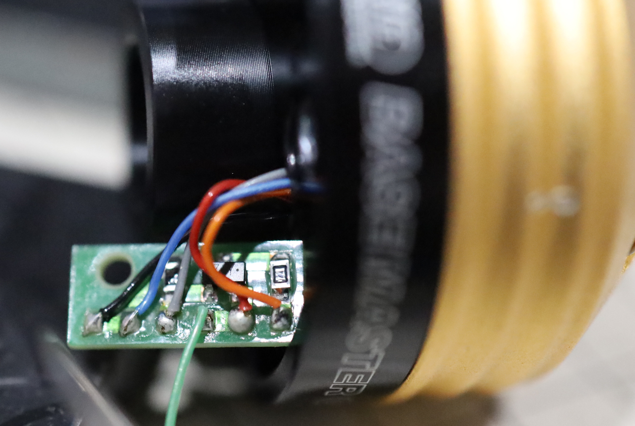
The bottom disassembly was very similar, although there wasn't the plastic isolation measures used in the conductive model. This exposed a slightly more complex PCB with a few SMD's mounted on it.
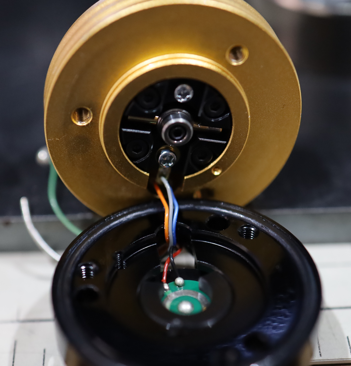
The middle housing was attached with 3 cap head M4 screws rather than 2 on the lesser model. Removing them exposed an electrically conductive spring and the Kinematic assembly.
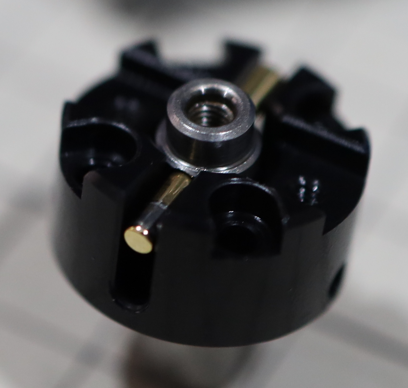
This assembly consisted of two gold plated pins held in contact by the spring force, arranged at right angles to each other. Depressing the plunger would break the contact between these two pins, and trigger the unit. This means there is always a small current flowing when the unit is idle, so removing the batteries for storage would be smart. I'll also note that there looks like there is wear on one of the pins, but it is actually relief ground into the surface to allow it to fit in the hole cross drilled in the plunger. The other end was too large to slide through the hole, so I suspect there may be some kind of profile curvature or opposing tapers going on with these pins. Again, this is where a really knowledgeable Kinematics Engineer might have something fascinating to explain.
I was able to reassemble both units without any trouble, they seemed fully functional and as they were both in a compromised state I have no idea how much the disassembly may have affected their accuracy. Because of the o-rings and changes to the screw torque it is almost assured that opening them will ruin their calibrated height, so if you are going to open yours have a plan in place to recalibrate or compensate for any changes (the offset once securely assembled will likely not change, so being 50.000 or 50.097 doesn't matter to a DRO as long as you know what that offset is, and it is repeatable.)
I hope this helps someone!
They are well built, and there is very little that can go wrong, but I see broken ones advertised all the time and picked up some of the cheaper ones so I could tear them down and answer my curiosity. I thought I should try and document this in hopes of it being helpful to someone or at least be interesting how they chose to achieve their purpose.
These units have been recently updated, I suspect the new models only added additional LED's to improve visibility and are internally unchanged, but do not know this as a fact.
The difference between these two is that the base model uses a continuity circuit that requires a conductive path from the base through your machine and tooling to complete the path when coming into contact with the top plunger. The Gold version uses a more sophisticated system that has a kinematic structure internally, and only requires a minimal force on the plunger to break that contact. So no conductive path is required with the Gold version, which may be important if your machine is insulated or uses non-conductive tooling.
I will note that a vast majority of the Gold units I see for sale have experienced damage to the ceramic contact disk inset in the top of the plunger. It is not a user serviceable part, and seems pretty sensitive to crashing, so be aware of this before choosing one of these. BIG Daishawa does not offer a replacement part here, so you are forced to exchange the entire unit at a very high cost. Hopefully this post will help those who have experienced damage to institute their own repair rather than junk an otherwise functional little unit. I will document my own attempts at refurbishing these units at a later date.
Also, due to the aggressive downsampling of this forum all the images are deep linked. If they don't appear for you I apologize, complain to the forum for being so resource restrictive at the time of this posting. Okay, on to the teardown.
The BaseMaster BM-50 has a single rubber plug directly opposite the LED on the top housing. Removing that exposes a 1.5mm hex socket set screw. I assumed this was the height adjusting screw (both of these units are shipped from the factory at 50mm to within a micron) but it is actually the plunge depth adjustment screw.
The bottom shows three embedded magnets and three potted holes. These are actually rubber plugs with a very thin layer of black sealant. Removing these plugs exposes three M4 cap head screws. Removing these screws allows the base to detach.
It is connected electrically to the middle housing by a wire soldered to a spring loaded ring that is press fit into a recess in the bottom block. This is easily removed with a sharp object. There is an o-ring to seal it (all these sections are similarly sealed) and there are plastic insulators to prevent the 3 screws from shorting between the sections.
Inside the middle housing there is a tiny 'circuit board' with a single surface mount component. I believe it is a transistor, my camera just wasn't up to the task of capturing the markings, I will try to document this better when I repair and modify these.
Two more cap head screws fasten the middle and upper housings, removing them exposes the plunger. There is a spring that is captured between these two housings and is what helps with both the conductive path and the backpressure of the plunger compression. No plunger depression is required on this unit to trigger the LED, it is a purely conductive trigger.
The plunger is rotationally locked by a pin that fits in a slot in the plunger, and has what appears to be a precision machined set of surfaces to ensure it always returns to the same height after being depressed. This consists of a conical area turned on the shaft that seats in a matching ring, divided into four segments. I don't have enough knowledge of Kinematics to explain the logic of this segmented arrangement, but I'd imagine there is an interesting reason for it to be broken up like this.
The plunger is threaded axially with a standard M4 thread that the (missing in this patient) disk shaped upper tool contact surface screws in to. I speculate that the height is dialed in at the factory by using the travel adjustment screw on the side to lock the plunger in place, then it is directly ground to height. I base this on a lack of any Loctite residue on the threads and the uniform grinding marks on a new example of this model. It is quite possible that they set the height just using thread friction and careful manufacturing though. I mention this in case you have a crashed unit with some damage to this contact surface, unscrewing it a few turns with some Loctite and regrinding it with the plunger locked in place may return it to the fray.
Okay, our next subject is the Gold version. Right off the bat I can see a circuit board through the (2xSR44) battery compartment. There is no plunger depth adjustment screw, this model again has a lapped ceramic disk inlaid in the top of the plunger, so not a good candidate to grinding into spec I think. The contact surface is threaded into the plunger with a smaller M3 thread. I do believe a small amount of thread lock was detectable on the threads, but it wasn't completely clear.
The bottom disassembly was very similar, although there wasn't the plastic isolation measures used in the conductive model. This exposed a slightly more complex PCB with a few SMD's mounted on it.
The middle housing was attached with 3 cap head M4 screws rather than 2 on the lesser model. Removing them exposed an electrically conductive spring and the Kinematic assembly.
This assembly consisted of two gold plated pins held in contact by the spring force, arranged at right angles to each other. Depressing the plunger would break the contact between these two pins, and trigger the unit. This means there is always a small current flowing when the unit is idle, so removing the batteries for storage would be smart. I'll also note that there looks like there is wear on one of the pins, but it is actually relief ground into the surface to allow it to fit in the hole cross drilled in the plunger. The other end was too large to slide through the hole, so I suspect there may be some kind of profile curvature or opposing tapers going on with these pins. Again, this is where a really knowledgeable Kinematics Engineer might have something fascinating to explain.
I was able to reassemble both units without any trouble, they seemed fully functional and as they were both in a compromised state I have no idea how much the disassembly may have affected their accuracy. Because of the o-rings and changes to the screw torque it is almost assured that opening them will ruin their calibrated height, so if you are going to open yours have a plan in place to recalibrate or compensate for any changes (the offset once securely assembled will likely not change, so being 50.000 or 50.097 doesn't matter to a DRO as long as you know what that offset is, and it is repeatable.)
I hope this helps someone!