What's new
What's new

BMC30 spindle rebuild

jakefreese

Hot Rolled
Joined
Aug 4, 2012
Location
TEXAS
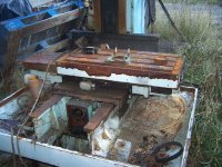
I am in the process of rebuilding the spindle in my 1992 blue Hurco BMC-30 Is there anyone here with experience this deep into the machine ?

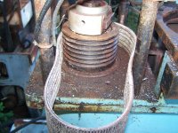
The upper set of lower spindle bearings has checked out on me. Its got a bunch of hours on it, it did not get crashed, and it gets babied. I found replacement bearings which are on the way.

I was a bit shocked at the price of the belleville washers from Hurco $5 ea and there are 128 of them. They were stacked 2 high then 2 inverted so they were in packs of 4. I found some at McMaster that measure the dimensions and have #1388 lbs working load and #1810 lbs flat. I do not have a way to measure the force of the washers I currently have and do not know what the retention force was before it was taken apart this is a CAT40 spindle. I might buy a strain gauge to measure the existing ones to get an idea.

Next thing is bearing preload on both the lower set of bearings and the upper. Do any of you have an idea what the bearing preload should be ? The lowers are 2 pairs of 7014 bearings and the upper is a single pair of 7012. All 3 sets had thrust pointing at each other. Grease is the next question, this had a white soapy feeling grease in the bearings. A CNC tech told me what it more than likely was and I forgot. What is a reccomended grease for these now days ?

Last thing is the drive dog on the end of the spindle, there is some wear on it. What is considered the replacement point on these ? I need to see if I can buy it or if it will have to be made.

I am planning on monitoring 3 axis vibration and temperature during the break-in to see if a balance job needs to be performed on it, and also double check the spindle taper while it is out. The machine went from happy and and cutting nicely to angry and looking like things were cut with a chisel quickly and in the process it was eating the polymide bearing cage.

Thanks in advance everyone!
 
@JHOLLAND1 I can not send you a PM for some reason. I am also looking for the Y axis ball screw support for non-drive end. What year BMC-20 are yours ? mine is 1992 light blue machine. 6000K spindle that has the 6 groove drive pulley.
 
The grease is probably Kluber Isoflex NBU 15. Count the number of openings in the bearing cage and only squirt in 20% of that in between the balls. I would ask Hurco for a technical sheet on Spindle bearing replacement Spec's and how too. I would also watch where those run out marks are as you take them of the spindle shaft. Once the bearings are off the shaft, set the spindle in Ground V-Blocks and measure (turn by hand using a .0001" indicator) the TIR of the bearing race location and the cat 40 taper. It should be less then .0002".

Also do the rebuild in a clean area of the shop on a clean work bench. I would buy an inexpensive bearing heater or make one. I made one years ago out of 4" aluminum turned down on a 1/2" taper. I bored a hole in the big end and inserted a 1/2" heat sink I bought from Grainger.


Thanks Richard!!

I did buy Isoflex NBU-15 for it and found the NSK tech manual for the bearings that states the fill for the bearings. Once everything has been cleaned once it will be moved into the room that is cleaner than where the machines are. All these areas of the shop are kept pretty clean and there all climate controlled.

I will check the spindle runout today, I am still waiting on a pin spanner wrench to come in and a couple other parts before I get to start re-assembling. Hurco did not have any documentation that they would provide on this spindle beyond the manual which there is no information in there to answer the questions of bearing preload or procedures for the spindle. The NSK tech manual does have the range of what the preload should be based on the bearings and operational characteristics. I am going to work through that then have a mechanical engineer co-worker peer check me on my values. There is a spacer between the bottom bearing and the end of the spindle shaft that I found cracked that I am going to start working on this week. It looks like one of the thrust washers from a ball bearing thrust washer assembly. I bought a ball bearing thrust bearing assembly that is close in size, which I will take 3mm off the OD and surface grind a couple mm off the thickness. IF that does not work out like I need it to I will probably get a piece of 4140 and make a new one. It is more of a shield from the bottom bearing to the spindle face and sits right above the labyrinth spindle nose seal package

Thank you everyone for the help!
 
Next time you do a job like this mark where the nut was before removing it. Use a scribe to make 2 lines. That was where the factory set it. Also micrometer the bearings to be sure they are the same size. I found these on You Tube. It's a Hurco spindle rebuilding.
 
pics
 

Attachments

  • 100_3246.JPG
    100_3246.JPG
    983.8 KB · Views: 10
  • 100_3247.JPG
    100_3247.JPG
    847.4 KB · Views: 10
  • 100_3248.JPG
    100_3248.JPG
    781 KB · Views: 12
  • 100_3249.JPG
    100_3249.JPG
    863.1 KB · Views: 12
  • 100_3250.JPG
    100_3250.JPG
    704.2 KB · Views: 12
  • 100_3251.JPG
    100_3251.JPG
    783.3 KB · Views: 10
  • 100_3252.JPG
    100_3252.JPG
    606.1 KB · Views: 10
  • 100_3253.JPG
    100_3253.JPG
    654.6 KB · Views: 10
  • 100_3254.JPG
    100_3254.JPG
    898.4 KB · Views: 10
  • 100_3255.JPG
    100_3255.JPG
    664 KB · Views: 10
I taught scraping classes at Hurco years ago. They said made on the label Made in USA or assembled in the USA, but the casting, they were built back then at Leadwell in Taiwan, disassembled and and shipped to Indianapolis. Hurco installed their controls and assembled there too. The spindles were probably made in Taiwan. That's why there is no tech info on the spindles.
 
Thanks again Richard, That is the video series that encouraged me to tackle it. I did mark where all the nuts were before disassembly and took measurements from stationary points. I wanted to find what pre-load should be in case someone else has worked on this spindle. I have only had the machine 8 years.

@JHOLLAND1 That is the little brother to this machine. I am not sure the spindle is the same, that one does not appear to have had a spindle cooler on it so the spindle barrel is different. I do not know if the rotating element would be the same, if it is I would be interested in it. I do need a non-drive end ball screw support, I will take a picture of one of mine. Per my manual all 3 axis supports are the same. They have a pair of 6206ZZ bearings in them.
 
I taught scraping classes at Hurco years ago. They said made on the label Made in USA or assembled in the USA, but the casting, they were built back then at Leadwell in Taiwan, disassembled and and shipped to Indianapolis. Hurco installed their controls and assembled there too. The spindles were probably made in Taiwan. That's why there is no tech info on the spindles.
Seems like there is very little info on this vintage of machine, That makes sense if they got complete spindles from Taiwan and have no design control or technical information on them, they were not confident on what spindle it could be either.

I would not mind a new Hurco, A buddy has VMX that is a couple years old that they really like.
 
my two machines have 40 taper sockets-which i do not think incorporated active spindle cooling
if you get pics of y screw support--i will take pics of apparatus and post

my other bmc20 is inside stored and newer with removable swarf tray wings--not sure if this is significant
 
I called and left a message with Eric Olsen in service at Compact machine in Plano TX as they are major Leadwell Distributors. I taught a scraping class there a while back. He said if you take a picture of the Hurco name plate on the Electrical panel and email it to him he will forward it to Leadwell. Like I said before Leadwell made Hurco machines years ago. He said it is a pretty likely Leadwell can help as he has sent pictures to them before on Hurco's that were made by them and they helped. He said they also can supply the washers... Please give him a call. 800-450-4120 and he can give you his email and info direct, so I don't forget what he said. lol Rich
 
Last edited:
Eric at Compact set me up! They had a spindle spacer that was close enough, and was able to provide the preload data for those bearings. Which preload is supposed to be 8-12 microns, I am still looking to find the best way to do that. One thought was turn of the nut, it is 1.5mm pitch. With the 70mm shaft it should be 2.4 degrees of rotation, circumferential travel should be 1.465mm, once all the slack is out. I question accurately measuring the stackup of bearings, spacers, and the preload nut.

The above videos appear to be the exact spindle that I have. The lower bearing preload nut is the same also. I thought the socket cap screws were the locking mechanism so the nut can not turn and that is not what sets the preload. Other rotating machinery that I have set preload on we have always had crush washers, torque values, turn of the nut values, rotational force values to determine how much preload.

Thanks again for all the help! It should be going back together on Sunday.
 
Last edited:
Sorry if Im late to the party. You get this built yesterday? The vidoes leave a bunch to be desired, and as you pointed out there is plenty of items not addressed. While this is a simple spindle design, there is still a lot to know when it comes to successfully completing a quality rebuild. If you already got it together the proof will be in the test runs, if its apart and you still have questions let me know.
 
I did not get back to it over the weekend. I spent an hour or so cleaning parts and still have more cleaning to do. I plan on heating the bearings to set them to ensure that I can get them seated properly without having to force them, I am going to try to get the aluminum cone fabbed up for the bearing heater in the next couple days and finish cleaning. At this point I do not have any specific items I have questions on assembly. Break-in was one that I was questioning as it seems like many have there method that works for them. I was originally going to do the 10% RPM and run till temperatures normalize and keep increasing steps. I have also seen where on the initial start they will run the spindle to 100% speed as fast as possible to get the grease slung to the outside of the bearings and ensure the balls do not skid, this gets done a couple times then back to the incremental run and normalize temperature. I thought proper preload is what sets the bearings up to not skid. I do have the vibration monitoring to watch vibration levels also.
 
Ok, Sounds like you have a plan. Just make sure all critical surfaces are good (.002mm or less), bearing journals, shoulders, spacers, etc.

A couple things I need to bring up.
First the marking the nut to the shaft strategy is flawed and you are destined to create problems. Bearings are very tight tolerance in every dimension except width, the new ones will not be the same as the old ones. That makes your stackup a different length which lands that nut in a different spot. If you try to line the nut up with your previous mark, you will be either unloaded or too tight on the nut. The only exception to this is if you measured everything, happened to be taller and cut your spacer(s) down to compensate, which is much harder with no upside.

Second, In this spindle (and most) you dont set preload by bringing the nut tight and then going a predetermined distance beyond that, the preload is determined by the length of the spacers between the bearings. For example if the spacers are even and you tighten the nut, then try to go another 1/3 rotation, all you have done is distort the spacers, tweak the shaft and create issues, runout etc. When you tightened the nut, the bearings were preloaded to the amount ground into them by the mfg, which in this case would be perfectly fine. Now if you wanted to increase the preload you would grind the inner spacer shorter than the outer spacer by the amount you want to increase it.

Also, since like I said before the stackup height will be different so make sure you measure and cut your cover for the correct capture on the outer races before you assemble anything.
 
As far as break in.
Plug (start/stop) the spindle a dozen times or so to distribute the grease.
Turn it on and let it run a very goodly speed for an hour. Check every five-ten minutes with a temp probe or your hand.
There is no "break in" here. It is put together right or it is wrong.
A top level car racing guy I asked this question once. He told me "We make one 1/2 to 3/4 throttle pass to see it it holds. Then it is time to go racing."
I can not stress enough that there is no break in for a spindle bearing. Only break down which means short life.

As noted above marking the nut is a no-go.
You may want to blue the nut and hand scrape its working surface as often the threads and or nut are "drunken" so this moves the contact at tight as bearing thickness changes.
This falls into "crazy land" in rebuild time but I do it anyways as a check.

I have gotten away with such terrible things in rebuilding spindles over the last 50+ years.
2000 running hours and 80,000 hours are the done good and not so good.
Bob
 
Last edited:
There are multiple schools of though on spindle bearing "break in".

When it comes to engines I subscribe to what Bob stated. But its not often that engines use ball bearings, and when they do they aren't usually grease lubricated so its not exactly a fair comparison.

A properly set bearing doesn't need "break in" per say, but when there is grease put in the ball path it must be push out and distributed away. This generates heat and additional resistance.

This heat generation can depend on a lot of things, preload, bearing stack up style, angular contact or roller, lubrication method, etc.

The main reason for starting "break in" slow is its much cheaper and safer to identify issues at 1000rpm than 10000rpm. The strategy can differ when its a 120,000rpm spindle.

Remember, when you touch the housing, the shaft is much hotter, and the inner race is even hotter than that. This is especially true if there is a chiller system in the housing.

Just start slow, monitor heat, and adjust rpm accordingly.

A good result would be low taper runout, no axial or radial play, drawbar force in spec, no significant vibration, heat or noise. And ultimately a good part made.


Back
Top