What's new
What's new

Brainard Small Hand Milling Machine

More thoughts on the age of this mill:
Looking online, very little remains of pre-Becker Brainard machines. Vintage Machinery has the most information in one place (Brainard Milling Machine Co. - History | VintageMachinery.org) but from there I've been looking to see what other machines are still out there from the 1871-1899 era. In general, anything pre-1871 would have been when Amos Brainard was still under Union Vise's roof (and it seems that he was only with them since 1865), and anything after 1899 would have been after Becker bought the company. Becker-Brainard's have showed up from time to time online, but not much from when it was "just" Brainard.

Brainard horizontal milling machine co.
This 2016 thread shows what seems to be a much earlier Brainard. Note that the base and frame casting are much different. I imagine this might even be the shop-made design that Amos Brainard developed at Union Vise, because here:
Patent Images
We see a 1887 patent showing the base/frame design that my Small Hand Mill and later Becker-type mills were modeled after. 1887-1899 isn't a huge window, but I'm a little more certain that that's where my mill falls.

Determining the exact age of the machine might be of little consequence, if at all possible, but putting a little more identity to the machine has merit I think. Often we have so little of the legitimate history of our machines in who owned them and what they made, that just knowing how the machine began life is all you can do. I think the historical aspect of machines like this is also fascinating in seeing what the world was like when the machine was built and later through the years. How the machine influenced the world and how the world influenced the machine.

Often the age of these machines takes me by surprise. Not so much how 'long' ago it was... but how NOT long ago! Our family business goes back as far as 1858, and the other day I found a sales receipt for our company from 1901 addressed to a company in Oklahoma TERITORY. It's interesting to think that there really wasn't that much time between "cowboys and Indians," and world wars. Every time I stand in front of my 1909 Hendey, I marvel that when it was new, the idea of a "World War" was still futuristic, and the Titanic hadn't even sailed.

The industrial revolution was active for awhile, but looking at catalogs and remaining machines it seems that there was a serious surge in technology around the 1880-1900 era. Lots of iron was cast then that was obsolete and replaced by the first world war. Same happened when the second world war happened and then the cold war. Sometimes seeing how these machines fit into those eras gives a lot of perspective as to how far they/we have come, or how little has changed.

I'm still young, but the older I get the more I find that "history" is much closer than you think and it's prudent to be comfortable with it while also knowing that the future is constantly changing and intangible. It seems all to often people see it the other way around: the past no longer exists and the future is now.
 
I've got the knee gib assembly built... well at least the first one. It actually turned out functionally good and allows the knee to be held in place without a C-clamp. The downsides is that the two center mounting holes are off, and my blank ended up being undersized by 1/4" which made the dovetail a bit thinner than I had hoped. It has about 5/8" width of contact with the columns 1 1/8" wide dovetail. The mounting holes are spot-on dimensionally but apparently the holes in the knee casting are not. Not yet sure if I'll plug and re-drill the holes, slightly elongate them, or just make a new piece all together. The top and bottom holes are good, so I think the easiest way to locate the middle two would be to use thread-transfer screws.
20220106_231251.jpg
20220106_231301.jpg
20220106_233452.jpg

With more parts filling in blanks, I also found that the gear I chose for the vertical movement pinion is going to be way too small. I had originally thought it was a little over-sized at 1 3/4" OD, but my math was off as the correct diameter should be closer to 3 1/4". I intentionally hadn't drilled the mounting holes in the gear rack yet, but I suppose I could either drill new mounting holes in the column to shift the gear rack over, or make a little adapter plate to do the same, but first I want to see if I can get a gear of the correct size as a larger gear will give more sensitive movement and require less modification.

Jobs like this are "fun," like building a bridge from the opposite side of a canyon from an existing road and trying to meet in the middle, but doing it like the bridge was always there. Even when a few dimensions don't pan out, you still have others that did and give more solid progress.
 
When I saved that casting I wasn't sure what was going to happen to it but I'm glad that it fell into good hands. Great work.
 
Not a lot of developments as I've been focused on getting other projects progressing or done, but one of those was getting my 16" Hendey running again, so I've started roughing out the spindle. More on that in it's separate thread, but with it I'll need to make a pair of take-up nuts for it, which I have material for, and I also want to get started on the spindle's cone pulley.

I've been trying to find the medium between what I think was original to this mill, the upper cone pulley I bought, and materials I have on hand. By the catalog picture, it's a 4 step pulley. Other models with the same frame had a five step pulley, but it's a tight squeeze and since I already bought a 4 step pulley for the top, that's what we're going with. The upper cone pulley will be slightly larger than the lower, which looks to be appropriate with the catalog photo. The question now is using the upper cone as my base line, what size's of steps will fit down bellow (considering that they all scale down the same so the belt shifts properly).

The construction method I'll be going with is to weld the cone together out of steel pipe and disc sections. The smallest step will either be a solid steel piece pressed and welded to the hub, or cut all from the same piece, so I'm only looking at 3 pipe sections and 3 rings to weld together. I took inventory of my pipe drops and will need to find more once I know which sizes I'll need. This could also affect things as I'll need to find pipe with the OD on size for typical 1/4" wall tubing. I plan to starting with the smallest piece, weld one piece then true it up in the lathe and cut the OD to size before welding the next, so I can keep accumulative error to a minimum, so I need enough material for that. Walls between 1/4" and 1/8" are ok IMO and well within my ability to cut and weld the sections together. Thicker wall tubing is of course available, but more expensive and most of it would end up in the chip bin anyway, so I'm only considering that if I need to create a step in a size that isn't available. The discs I'm considering outsourcing to a shop with a plasma table as they could essentially cut them all out of one disc with little to no scrap (Russian nesting doll style). If it came down to it, I have 1/4" plate that I can oxy-ace torch out and clean up on the lathe. The hub will be a 1 1/2" ID x 8" long tube, 2 to 3" OD depending what tubing I have. The trickiest part with it would be broaching an 8" keyway through it (no shaper on hand), so I might end up undercutting the middle and just broaching the ends. Doing that I'll need to start with a larger OD. After It's all done, I'll try balancing it by welding and trimming weights to the ID.

I'm optimistic that the end result will be plenty functional and look close enough to an original cast cone. Worst case, it gets the machine functional and I can make a pattern and cast an iron cone later, and this exercise will help me nail down dimensions.
 
Last edited:
N. B.

First, a general comment - you wrote:
" I have a bad habit of loading up on rebuild/restore projects, but in the last couple years it feels like I've been catching up and getting a rhythm."

I suggest that many forum members can see themselves in that statement !

About internal keyways without benefit of a shaper:

Decades ago, a ( then ) old timer showed me how to "make do" with a boring bar in a lathe. You run the carriage back and forth to stroke your ersatz "shaper". Technique is to cut the keyway horizontal, so the manual cross feed controlled the depth of cut.

Obviously also works with external keyways.

Note that this is a 100% manual operation. Lots of patient cranking of handwheels...

John Ruth
 
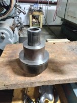
I rounded up all the pieces for the spindle step pulley and started on it tonight. For the hub and first step, I have a 2 1/4" od pipe, roughly 8" long. The OD and ID have just enough material for a tiny finish pass. The next 4" step I cut out of a solid 4" drop I had and bored to fit over the hub. The next step is some 6" thick wall tubing that will trim down to 5 3/4". It already had a flange nicely welded inside that trimmed up nicely. Going to weld these three pieces together next, and then I have a piece of pipe for the last 7 1/2" step. The flange for it I'll cut out of a solid disc I have. I'm thinking a rotary table will do best so I can save the center for something else.
20230207_193217.jpg
20230207_193205.jpg
Making some progress.

While rounding up rounds and drops for this project, I also located some pieces for a couple of the pulleys on my Brown & Sharpe #12 production mill, which like this one needs both step pulleys replaced, as well as a pair of step pulleys for it's power feed. Luckily they are all 3 step pulleys, so a little simpler, but more on that later. I've decided both of these mills will use some bearings and shafts I salvaged from some old shoe finish machines that went to the scrap pile. The bearings are nice iron ones with sprocket chain oiling dipers inside and fit 1 5/16" shaft.
 
I rounded up all the pieces for the spindle step pulley and started on it tonight. For the hub and first step, I have a 2 1/4" od pipe, roughly 8" long. The OD and ID have just enough material for a tiny finish pass. The next 4" step I cut out of a solid 4" drop I had and bored to fit over the hub. The next step is some 6" thick wall tubing that will trim down to 5 3/4". It already had a flange nicely welded inside that trimmed up nicely. Going to weld these three pieces together next, and then I have a piece of pipe for the last 7 1/2" step. The flange for it I'll cut out of a solid disc I have. I'm thinking a rotary table will do best so I can save the center for something else.
View attachment 386542
View attachment 386543
Making some progress.

While rounding up rounds and drops for this project, I also located some pieces for a couple of the pulleys on my Brown & Sharpe #12 production mill, which like this one needs both step pulleys replaced, as well as a pair of step pulleys for it's power feed. Luckily they are all 3 step pulleys, so a little simpler, but more on that later. I've decided both of these mills will use some bearings and shafts I salvaged from some old shoe finish machines that went to the scrap pile. The bearings are nice iron ones with sprocket chain oiling dipers inside and fit 1 5/16" shaft.
we're watching!
 
What kind of welder will you be using? I only have experience with Oxy/Act and to do those pieces with it I'd be holding a freaking rocket, lol.
 
What kind of welder will you be using? I only have experience with Oxy/Act and to do those pieces with it I'd be holding a freaking rocket, lol.
Wire feed MIG. We have an old Miller Shopmaster 300 AC/DC with a wire feeder on top and a high frequency box and cooler beside it for TIG. I'm turning a little bit of a V on either side of each seam then I'll smooth it back down afterwards. We have a couple of TIG machines too that I need practice with. The MIG is just so handy to zip things together. I like using the OxyAce for casting repairs. It takes some fuel, but I've learned to use a rose-bud tip to get the casting as hot as possible so the filler rod just flows into the seem.
 
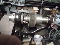
I got the hub and the first two steps welded and trimmed to size. Tried some different settings and used a lazy-susan platform to spin the assembly, but still ended up with some voids. At least I know there's good penetration! It's just cosmetic but I might go back and fill them in some more when I get the last two steps finished. I left a 1/4" radius filet in the corners too. I test fit it with the spindle and determined what needed more trimming. I want the hub and cone to take up as much room as is available, but still spin free and not inhibit the spindles adjustments.

The spindle face has 3/8" extra material on it that I'm trying to decide what to do with. The spindle will move fore or aft in relation to the nose ring depending on the bearing take up, so I want some extra material and I can give it some geometry to blend into the nose ring too. Extra material is also good if the nose or taper ever needs to be trimmed upin the future, but the further the nose sticks out, the less real estate I have to work with in the cross travel.

At one point I thought about adding threaded holes to the spindle face too for heavy cutting applications, but the more I think about it it shouldn't be nessisary. If the taper and 3/8" draw bar aren't enough to keep the tool in.... I need a bigger mill!
 

Attachments

  • 20230210_215341.jpg
    20230210_215341.jpg
    1.1 MB · Views: 17
  • 20230210_215048.jpg
    20230210_215048.jpg
    4 MB · Views: 17
  • 20230210_215142.jpg
    20230210_215142.jpg
    2 MB · Views: 17
Last edited:
I finally got the spindle take up nuts made. The 16 TPI threads fit nicely and the last detail will be to add four spanner wrench holes to each nut, keeping the design consistent with the spindle bearing nut (no flats, etc.) They're just mild steel.
20231016_210851.jpg
20231016_211956.jpg
At some point I might replace the bearing nut as the rusty part you see in the picture is a steel ring, pressed over the broken sectons of the original iron nut as a repair, but the old repair seems to have held up well and kinda adds to the mills story.

Also been getting some more black paint on the base. After that I want to do a little gold stripping along some of the embellishments on the legs. Not a lot, but just enough to help their mild scrollwork design stand out. Eventually when I get the door replaced (dreaming of an iron casting) the raised lettering will be gold as well so the door and legs should go nicely together.

On that note, I'm torn between making a wood pattern, and drawing a CAD model to 3D print a plastic pattern from. It shouldn't be too difficult a design and I think both methods are within my skill set. With a properly drafted pattern, I will most likely build it around a mould board and then get a quote for a one-off iron casting. I'm also toying with the idea of pouring it myself from brass, which would be fun, but I'm not ready to get into sand casting just yet and would rather "outsource it". While brass kinda goes with the age and use of this mill, I think a solid brass door would be a little too flashy too, and an aluminum door would feel too much like a cheap replacement. While it isn't the original door, I'm hoping an iron one will be enough to fool myself. It's a shame that the door is gone as it holds so much of this mills identity, especially as there dosn't seem to be any others like it left, so reproducing the door feels a little like reproducing a lost title or VIN plate. Gotta do it right.

I've also been thinking a bit about jobs I could do on the mill. While it would be nice to use as a working display of sorts, I'd rather be able to do some "real work" on it. The light duty, hands on, and production aspects of it's use all play into it. There are plenty of job-shop jobs it COULD and likely will do, but not a lot of my day jobs product line fits its bill, at least not in a way that dosn't make our CNC and conventional mills roll their eyes out loud. So looking at other new avenues, as silly as it might sound I'm thinking about making some fixtures to make brass and aluminum men's combs. I have an approx. 5 ton benchtop mechanical die press from the 1900-1930 era ("Baird" I think) that would fit nicely beside this little mill and together with some specialized fixturing, I could see some "hand made" combs coming out easily, and the 125 year old tech kinda adds to the marketing appeal. Dunno yet. I don't have an affinity for men's combs, but I tend to enjoy the process of machining more than the results of it.
 
Brainard door model 1.png
Brainard hand mill door detail.jpg
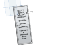
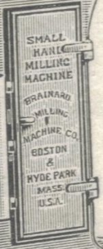
Here's my current progress modeling the side door, and a detail from the catalog photo I'm modeling it from. I don't think I'll get the exact same font, but I am trying to get the spacing and proportioning the same. I'm using the hinge locations and the opening the door covers to scale the model. Once it's complete I'll probably cut it in half and 3D print the whole thing in two pieces to be glued back together (due to the limited table size of our printers), or just print the more detailed sections of the model to attach to a plywood pattern (script blocks, hinges, etc.) The spot in the middle between "Milling" and Machine Co." is a key hole that was likely cast in before, but I'm thinking about leaving it out to simplify the cast and then machining it in afterwards. I'll still need to find a lock that looks like the original, as seen on some other Brainard survivors online.

Modeling this door isn't as challenging as I thought it would be, it just takes lots of back-and-forth comparing images and shifting things around.
 
It looks good, but the words "Brainard", "Milling" and "Machine Co." need to be stretched out more.
You can see that "Machine Co." almost goes from edge to edge.
Also "Machine Co." is not laid out in a simple arc/curve. It has more of a double curve to it.
Also "Mass." is a smaller size than "Boston & Hyde Park".

Rob
 

Attachments

  • Brainard hand mill 1b.jpeg
    Brainard hand mill 1b.jpeg
    67.6 KB · Views: 4
Last edited:
Wow, when I pulled that thing out of a basement near Frederick, Maryland, I never envisioned it would look that good. You've done amazing work on it. Can't wait to see a completed and operational.


Back
Top