Joseph Ryerson started out as a firm supplying tools, machinery, and metals in Chicago, Illinois. They went on to become a steel/metals supplier and eventually were absorbed into Inland Steel. Ryerson, to my knowledge, never manufactured any of the machine tools they sold. Ryerson was a big enough firm to have machinery builders add the Ryerson name onto the patterns for castings used to build the machinery. I have seen Ryerson ironworkers (a combination machine for punching, shearing, and notching of structural steel and steel used in other fabrication work). I have seen Ryerson's name on a fairly heavy old lathe in the engine room of a long-gone Great Lakes ore boat. I've seen a few Ryerson-branded camelback drills as well. I do not know when Ryerson stopped offering machinery with their name on it, nor do I know who was making the various machine tools and metal forming machinery for them.
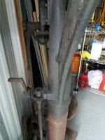
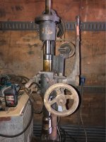
As has been noted in this thread, the basic design of camelback or upright drill was a common things with many manufacturers. Differences in things like power feed mechanism, back gearing, and table elevation mechanism were the major differences from one manufacturer to the next.
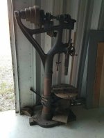
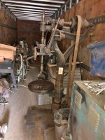
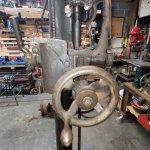
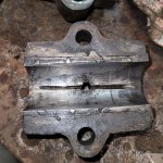
I'd say the OP's drill was used hard and put up wet, given the appearance of the table. The table is not original to the drill. Chances are the original table was either cratered by people who did not care about the boss' machinery to the point it was unusable. It is quite common on these old drills to find tables that make Swiss Cheese of the surface of the moon look like a newly surfaced ice skating rink. My guess is the table got to that point, and some enterprising soul made a replacement out of steel plate or maybe an undrilled pipe blind flange (an easy way to get hold of a thick and large diameter disc of cast iron or forged steel).
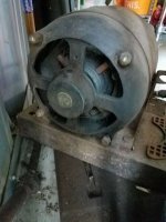
These camelback drills are amazing old machines in their own right. I own and use two of them: a 25" Cincinnati Bickford with original motor drive, and a 20" Barnes.
As I've posted here previously, these old camelback drills are way different than the modern v-belt driven tubular column drill presses that are in common use. Namely, these old drills with their deeper reduction of speed, produce a lot more torque, and if the flat belts are properly made up, are not too likely to slip if the drill grabs.
There is also a lot of stored energyin the driveline of these old drills. Even if the motor is switched off, there is some coasting down with a good deal of torque still there. Hence, anytime these old drills are used, clamping the work to the table or clamping the drill press vise to the table is the thing to do. These old drills with their considerable torque, will wind up a drill and the job and pull it free of a user's hand, or wind the user and his hand up with it. I keep an assortment of 'jewelry' in the form of tee nuts, clamping studs, steel clamping straps and similar by each of my camelback drills.
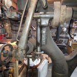
The other thing to address on these old drills is oiling before each use. Get to know all the oiling points on the drill press, and there will be a LOT of them on a drill with power feed and back gearing. I keep a pump oil can with a long spout and pointed nozzle by each drill press, filled with Tractor Hydraulic Oil (ISO 46 or ISO 68).
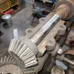
It is handy to have a short stepladder by the drill to access the uppermost oiling points. I'd suggest looking in the top of the crown gear (the spindle passes up thru this gear). There may be an oil hole in the web of this gear to oil the thrust washer between it and the top of the drill press frame. Blow out any oil holes with something like automotive brake parts cleaner and the thin tube 'wands' to make sure the oiling points are not choked with grunge. I run some automotive grease on the bevel pinion and crown gear as well as on the other open gearing on my camelback drills. A light greasing is about all that is needed. Open gear lube such as "Crater Compound" is really the ticket, but it is a sticky, messy proposition. For light use, some grease made for heavy automotive or heavy equipment service is OK in my opinion.
When not using the camelback drill, it is a good idea to run the belt off the cone pulleys. This will prevent the belt permanently stretching, particularly if a leather belt is used and weather is humid. When running the belt off the pulleys, try not to let it hand on the upper shaft bearings as these are usually oily.
These are great old drills, but need a bit more doing to use them safely and properly. They will push a large diameter drill thru steel with a surprisingly low motor horsepower driving them. Slower, perhaps, but for a home shop or small shop, the old drills work quite well. These are a 'real machine tool', not some light duty "import' drill press. As such, using one of these drills calls for a bit more setup in the form of securing the work to the table rather than making the mistake of hanging onto the job with one's hand. I use my camelback drills for running taper shank drills, counterbores and reamers on jobs such as drilling structural steel, fabrication work and blacksmith work. Years ago, I had a job to drill a bunch of 1 1/4" diameter holes thru some 5160 locomotive leaf springs. I made a simple jig and drilled 1/4" pilot holes thru the spring leaves. I then made a setup on the Cincinnati Bickford camelback drill and started pushing a 3/4" taper shank drill thru the spring material, followed by the 1 1/4" diameter drill. I was taking the chips away with a flat shovel and filling a wheelbarrow with them. The old camelback drill just kept right on, and the power feed and 'knockoff dog' made easy work of it. Great old machine tools.