Metalmagpie beat to the punch. I have a saying: what one man designed & put together, another man can figure out and take apart. This saying has its exceptions:
If what one man built has parts set in a casting, or imbedded in concrete, or welded in place... then some demolition to get things apart is needed. Getting it back
together again is going to be a bit more work.
Usually, the guys who designed and built old machinery leave a pretty good trail to follow in terms of getting it apart and back together again. Years ago (and I still do this), we made sketches and marked various parts as we took machinery apart for repair or to move it. Nowadays, everyone simply whips out their phone and photos or videos things. I also believe in match-marking parts. Even if two bearing caps are of the same design and will interchange, the wear on the bearings and shaft journals has made each cap unique to its bearing. Similarly, even if a bearing cap can be turned end-for-end and still bolt onto the bearing lower half and hold the shaft journal, it may not work or run well. Journals 'bed into' babbitted bearings, so match marking bearing caps is a good idea.
As I take split bearings apart, I keep a micrometer at hand. I mike each shim as it comes out, and keep each shim stack separate. Even if I wind up doing some scraping on the babbitted bearings and polish the journals that run in them, the original shims give me a starting point.
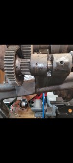
Back gearing designs varied with the different makers of machine tools. A popular design used on lathes as well as some camelback drills was to mount the back gear shaft on an eccentric. Moving the back gear lever rotated the eccentric(s) and moved the back gears in or out of engagement. Often, the back gear 'cluster' was cast as one piece and bore thru. It turned on a stationary shaft, and it was this shaft which was moved by the eccentric (or eccentrics in designs with one at either end of the shaft). These eccentrics might be taper-pinned or keyed to the shaft. FInding the small end of the taper pins and match marking with prick punch marks can save a person a lot of time in trying to figure out how things go back together. Pictures on a phone only go so far with parts like smaller taper pins and the holes they go into.
My other rule is: never force anything. It is unlikely that the people who designed the machinery relied on driving parts together with heavy press fits. Press fits or shrink fitted parts were used in machine designs, but the greatest majority of parts went together without needing to be pressed or beat on. Some parts may be put together with close fits, such that a little persuasion from a dead blow hammer or a piece of soft brass and steel hammer is needed. If something does not want to come apart with a little persuasion, look for clues. There may be a taper pin filed off flush and the end covered with varnished old oil/grease.
I enjoy working on old machinery because it is basic and was meant to be 'maintainable' by the machinists or mechanics who would be using it. The old machine tools date to a time when mechanics were expected to figure things out for themselves more often than not. "Owner's manuals" and the like were the exception, not the rule for many pieces of machinery. Mechanics back in those times were used to dealing with things like babbitted bearings, knowing how to cut and fit shims to adjust clearances, knowing how to oil a piece of machinery, knowing how to make up flat belting and get it to run properly on the pulleys, and similar.
I remember years ago, a mechanic in my old crew at the powerplant was telling me how he learned to work on automobile ignition systems. He had some old beater of a car when he was a kid, and it was a bucket of bolts he had put together from junkyard parts. He could not get the engine to start and run. His uncle gave him a hand. My friend said he was looking for timing marks on the engine flywheel and dampener pulley, trying to put number 1 cylinder on top dead center compression. He had been crawling over and under the car, looking for the timing marks and bumping the engine over and getting nowhere. His uncle came out of the house and showed him how to go about it, backwoods style, quick and easy. The uncle said something to the effect of " you don't need timing marks." He took out the spark plugs, and identified number 1 cylinder. The uncle 'corked' the sparkplug tapped hole with his finger and turned the engine over until he felt pressure building against his finger in that sparkplug hole. He rolled the engine until the pressure fell off, then backed up the crankshaft and slowly did it again. This gave him 'high cam' on the distributor's point cam. The uncle then set the points, gapping them with a matchbook cover. The engine fired right up. Once it was running, the uncle simply rolled the distributor and tried gunning the engine. No manual, no timing light, no dwell meter, no feeler gauges. Get in the car, take it for a drive, see how it pulls a hill and tweak the timing and carburetor by the roadside based on how the engine performed. This is how oldtimers did things. My friend needed a car, and was not in a position to pay a mechanic let along buy a good running car. His uncle was probably not much better off, and was used to having to work with what was at hand. It is a story that makes a good point. While my friend and his uncle might not have tuned the engine in that old beater of a car so it ran like a watch, it ran well enough so that my friend had a car to get around with. That is pretty much what working on old machinery is often about. We have no manufacturer's specs on what to set bearing clearances to, and with worn bearings and journals, we set clearances to what works or feels right. We do not have any specs on how tight a flat belt ought to be to transmit power, or what torque value to use when pulling down the bolts on parts of old machine tools. We go by our sense and feel and what the machinery tells us when it is running. As long as we do not get 'rammy' with hammers and similar, and as long as we do not get ahead of ourselves and mix up things like shims, bearing caps, and the like, we will generally do fine.