What's new
What's new

Converting a 20" I/M lathe to 30"

The long slow process of converting my 20" 10EE to a 30" bed is in the late stages of fitting the gearbox to the bed. It is well documented that the long beds need a 4.5 half round detail in the gearbox nose area for the inch/metric gear box to fit. The other part of the bed that needs attention at least on my particular bed is the butt end or the area where the end gearing resides.

The end gear housing on the I/M box is deeper than the cutout on the earlier bed design. This detail keeps the gearbox from centering on the mounting holes on the bed. With the bed in standard configuration the gear box is aligned with the holes at the very edge of engagement.

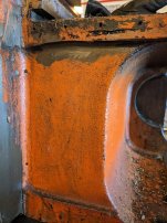
Looking at the end detail of both beds shows the difference, the older bed design has a flush face on the back vertical surface. The bed for the I/M gearbox has a sunken area below the headstock to allow the end gearing to move forward.

This has not been covered in much detail in the past or it has been lost over time?
 
Steve, maybe you're the first to do the conversion and write about it. Is this the 30" bed you bought 10 or 12 years ago? I remember when it was for sale. Did you have it reground?

Dave
 
Hi Dave,

Good memory,

I was on the fence about grinding the bed, I haven't. The wear on the bed is minimal, a bit more than my 20" original but IMO not worth the trouble.

I am going to assemble the lathe and see where it stands. The long delay was a whole host of things but, with the Series 62 and 13EE in reserve the 10EE could go dormant. That is the saving grace, it is also why I haven't been in much of a hurry to finish this!

I remember Orang? Did a long bed but that thread is gone? I know Hal, "swift220" did a I/M gearbox on a standard 30" I seen to recall at least one other project thru the years?

I am not good at taking pictures while I do work, this was the only pic I took on the mill.

StevePXL_20230221_213926582.jpg
 
That is a great photo. The 30" bed looks like a toy by comparison with the mill table. Please take some more photos. And while you are at it, please take a 360 around the shop. I'd love to see the 62 and 13EE in their native environment.
 
Pictures of orang's lathe is up in the sticker section.
Great pictures.
I also posted some pictures of the rear cut out needed for the gear box.

Hal
 
Last edited:
That is a great photo. The 30" bed looks like a toy by comparison with the mill table. Please take some more photos. And while you are at it, please take a 360 around the shop. I'd love to see the 62 and 13EE in their native environment.
When I thaw out I will take a spin around the shop, it is a real mess. That is on my K&T 320TF. The X axis was close to the end with the bed on the table where it is.

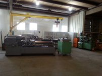
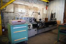
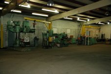
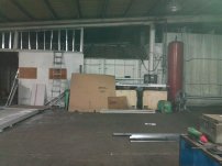
Here are the lathes in earlier times and a shot of the shop last month 20140512_114412.jpgPXL_20230204_202309187.jpg
 
It is still too cold for this native Californian to 'work' in the shop, under 50 is enough to make it difficult for many tasks.

I venture out and took a few pics of the area that needs attention. The 20" bed orange is as removed and the 30" has a bit of sanding/grinding to rough out the area of work. The recess in the 20" bed is about 3/16. PXL_20230225_193538638.jpgPXL_20230225_193647014.jpgPXL_20230225_193705678.jpg
 
Steve, thanks for sharing the photos of the shop. What a great space. What was its original purpose? I can't recall seeing a shop with that many jib cranes. The shops in the plants I worked in all had gantry cranes. I have been considering adding a wall-mounted jib crane to my shop.
 
This was the original home of the Piranha metal worker. Before that the brothers that started Piranha did beam detailing for Inland Steel here. This part of the building is a shed roof addition that connected the main shop to an old building that was part of the original 1936 brick building. The space in this part of the shop is 75X120, total under roof as it is about 30K sq ft.

The area with the jibs was also doing job sho welding, I know they made roll cages for Cat scrapers.

Here are a few old pics of the building one when it still had the brick front area. The shed roof drained 150 linear feet onto a flat roof with poor drainage, the water damage was extensive in both the roof and walls. The next pic is when I first put in the windows, it was a dungon before. 024.jpg027 (1).jpg024 (1).jpg
 
Russ,

I ain't all wine and roses, the care and feeding of a giant shop is all consuming.

Here are some pics of the shop while it was being set up, this took quite some time. The now outside wall on the west side of the shop was opened up with 12 glass block windows and insulated with 8" of rockwool. The insulation, steel studs and drywall were subbed out. In one of the pictures looking south you can see a big surface grinder at the far end. This whole place was open from the west to east wall of the main building.

The plan was to close off this area I call the 'tool room' from the other areas. In the back or north of this area there is a spray booth/sandblast area. The paint/blast rooms are seperated by a plenum area with a roof mounted exhaust fan. This area was also sheeted and insulated to the tool room. The east perimiter of the tool room is defined by a row of columns that also support a bridge crane. This row of columns is where the main building and the shed roof join. The siding was removed from the main building when the tool room was enclosed. To close this area up with siding would have worked but, limit access to both areas. I cae up with the idea of using overhead doors in most cells to close the area off. There are 3-16X12' doors and one 14X24' door in this wall, one cell was sheeted.

The surface grinder was enclosed in its own room along side a small office on the south. The double doors allow a forklift to enter the grinding room and, there is a 10X12 door to the outside. Next to the grinding room there is an electrical utility room.

The building was cold storage for years before I came along. There were several cranes both bridge and jibs with no hoists. I scrounged for hoist to get the jibs and bridge in the tool room functional, the jibs have 1/2 hoists, the bridge is a 3 ton with two 2 ton hoists. I put in a wirelees control system for the bridge, that is the only way to go IMHO.

Excluding the walls/doors insulation everything was done by yours truly. Electrical, plumbing, mechanical, rigging, etc. It is still a work in progress, the tool room has evloved over time. The next area of development is perhaps an office/lounge area.IMG_4001a (1).jpg025.jpg034.jpg019.jpg
 
Along with the bed I wanted to streamline the lathe to get rid of the external drive housing. This lathe was originally shipped with a module drive in the JIC cabinet. At some point the lathe was converted to a Fincor solid state drive in a smaller Hoffman enclosure that was raised behind the lathe on uni-strut. My old pics of this set up have gone missing. When I moved the 10EE to its present location I strapped the Hoffman box to the back of the headstock like the JIC cabinet. I was never fond of these from an astetic view. The 10EE is a very graceful machine and these added boxes while practical are IMHO an eyesore.

The drive has been relocated to the electrical bay in the base. The drives, an armature drive the larger orange/black and field drive small black to the left along with the field loss relay and other components. The meters that were on the Hoffman box will go in a small housing above the headstock.

The last version of the Hoffman box on the lathe, the drive in the box and the drive relocated.PXL_20211107_203130961.jpgPXL_20211108_195443007.jpgPXL_20211120_225029484.MP.jpg
 
It's impressive that the jib crane could lift the bed off the mill onto the base casting 10' away! Those beds are not light. I've lifted them with a 2-ton cherry picker, and it was right at the limit of what the cherry picker could handle.


Back
Top