What's new
What's new

Dealing with Mediocre CAD Files and Splines

How do you guys deal with mediocre cad files… got some files that would actually be really good except they are full of splines and have some illegal boundaries.

They machine Ok and make a pretty good part but leave blemishes that can’t be eliminated without redoing the cad model. Things that should be easy like adjusting a radius are impossible and certain cutter paths don’t work or have lots of “spikes” on the CAM. Things that should be done with basic 3 axis cutter paths are 5 axis style cutter paths.

Is there an effective way to tell customers and engineers to STOP drawing with splines.

I tried explain this to the customer and even sent a dxf that will eliminate most of the problems but they will have to the 3D work.
Sounds like you've handled this and your customer will accept the results. 👍
I would bet the person who drew the model was inexperienced and his model shows it. For the record, it is sometimes not possible to avoid splines altogether when a line or arc won't do. It doesn't matter if the design is in Creo, NX or GeorgeCAD. It's still up to the engineer or designer to produce a good model. If a model is garbage then the parts will be garbage, so if model fixing is possible, that's where up-charges come in. ;)
 
The example given is a spline. A circle projected onto a cylinder does not result in a circle definition. The projection parent is the circle.
Iso standards allow multiple stacked polylines for the same hole, inner and outer wall.

What the ever loving F@ck are you on about!
A circle projected onto any surface is, and will forever remain to be a circle when viewed from it's axis!
There is no spline! It is a circle!
 
I'm not sure what your beef is. This is a very complex math problem: the intersection of two cylinders, or bicylindric curves. https://mathcurve.com/courbes3d.gb/bicylindric/bicylindric.shtml

I think a spline is a very reasonable approximation of this complex geometry.
Great!
Another genius!
There ain't nothing complex about it!
If a circle cut through a surface was a circle when created, it MUST ALSO RESOLVE into a circle when projected back onto the 2D plane it was created from!
 
I always request the solid model. In Mastercam, and I'm sure in lots of other CAM systems, you can generate perfect circles at the top and bottom of any hole, even if it's at an angle through an organic surface.
Exactly!

Curiously, ADSK's own FeatureCAM will project a perfect, full 360 degree circle and recognize it as a drilled hole from the very model Inventor is unable to generate anything but a spline.
Of course, FC was not bred from the same morons who developed Inventor...

Projected arc is a spline .... my ass!
 
Projected arc is a spline .... my ass!
I think what they're getting at is the feature edge on the model is a spline; the circle projected into a cylindrical surface results in a 3D spline. But then if you project that spline onto a flat floor, you get a circle again. That's another thing Mastercam can do, and again I'm sure lots of other CADCAM as well, is project that spline flat (if that's all you have to work with) and then convert it to an arc or circle within a specified tolerance. I can usually use a tolerance smaller than my machine's step (.001mm).
 
I think what they're getting at is the feature edge on the model is a spline; the circle projected into a cylindrical surface results in a 3D spline. But then if you project that spline onto a flat floor, you get a circle again. That's another thing Mastercam can do, and again I'm sure lots of other CADCAM as well, is project that spline flat (if that's all you have to work with) and then convert it to an arc or circle within a specified tolerance. I can usually use a tolerance smaller than my machine's step (.001mm).

I understand their reasoning for the spline, but that does not make it correct!
If a 2D geometry - whatever that may be - is projected onto a 3D surface, and when the resulting 3D surface ( cutting edges or whatever ) is projected back onto the very same 2D plane, then it absolutely MUST RESOLVE into the identical 2D geometry it was created from!
It makes no difference what the 3D surface was, the projected 2D view in the drawing must be the same as the 2D geometry which created it!

What you are talking abut is a "fudging" of geometry when a true, honest-to-god spline is reconstructed (replaced ) by small linear or arc segments, but such thing is not at play here!
A circle cutting through a cylinder is not a spline but a circle ( not even 2 arcs of 180 degrees, rather one full circle btw ), therefore it requires no techno wizardry as suggested by others.

In addition, if I take the model from the example above and put it through Solidworks's drawing environment, save it as a DWG, it WILL ( correctly ) result in a circle!
 
Here you go.
View attachment 388213


The image clearly shows that the side view is not a circle, rather a spline with 50 control points as created by Autodesk Inventor.
No, it is not an AutoCAD problem, rather an Inventor problem created by morons who apparently should have no business writing code for a CAD application!
-Well...that is rather f'ed up isn't it? I used Inventor during one contract job and didn't notice this software "feature". I wouldn't like this regardless of the explanation. I will remember it if I ever have to use Inventor again. Thanks for posting this.
 
I understand their reasoning for the spline, but that does not make it correct!
If a 2D geometry - whatever that may be - is projected onto a 3D surface, and when the resulting 3D surface ( cutting edges or whatever ) is projected back onto the very same 2D plane, then it absolutely MUST RESOLVE into the identical 2D geometry it was created from!
Yes, that's what I mean. While it's on the 3D surface it's a spline; I believe that's what they were talking about.
 
“Regarding splines in Autocad: I have never needed to use splines in the 25 years I've been using autocad”

^^. This if we were machining some type of turbine blade to put a man on the moon I would happily use a spline if it served if it served a useful function. These parts are not doing that.

Anyways the customer liked the parts with some CAM features I have not used in the past. An initial order for 50+ parts came in the other day. If nothing else I’m gaining experience even thought the parts may not have been drawn to my stringent standards.
I'm a mechanical engineer in the aerospace and defense industry. Yes, they do like their splines and I understand them. We coat parts at work and I often have to make hard masking and tooling that is a close match. I rarely, if ever, have manufacturing drawings for these, but usually have decent step files. But not always. Sometimes symmetrical parts in CAD aren't actually symmetrical. I'm no CAD master either, so trying to match their model to a tee can be a pretty frustrating endeavor. It's rarely about the tolerances, but more about getting the model to build properly when there is some .000001 thick manifold body that is throwing a cut off or something.

Never heard complaints from the machinists though, so I'll take it.
 
To the OP; I didn't see this detailed; but what CAM system are you using? Can you share an image of one of the features that's being recognized as a spline? As a Fusion user myself, Spline is the last thing I want to be modeling with (unless I'm going for an organic shape)
 
Is there an effective way to tell customers and engineers to STOP drawing with splines.

I wouldn't tell them to STOP anything. I would SHOW them the issues it gives you on the manufacturing end. Call for a meeting and see how it goes.

If they make changes, great! If they don't, then ask if having the dents/divots is ok. If that's not ok, then you need to either see if it's worth your time repairing/patching their models to fix. The tricky part is if it costs you a bunch of money but risk losing them if you raise your price on future parts. No one wants to lose business. Is there a ton of work coming in where you feel ok sending them down the road? If so, it would free up time for you to work on more lucrative prospects. It also would stick it to them and if they are a smaller company, they'd probably take a step back and re-evaluate their approach.

I feel if you hammer through these issues to find a good workaround, then that makes you more capable. But it never hurts to discuss manufacturing issues like these with customers. It makes better designers out of them and keeps you from pulling your hair out.

We lost a potential customer because we quoted some parts with a premium because of CAD issues that they couldn't fix(also fusion360 models where there were gaps between surfaces that we couldn't repair either, redesign was not an option). Shortly after, we found an easy solution to the problem and programming would've been a breeze. Now we know.
 
To the OP; I didn't see this detailed; but what CAM system are you using? Can you share an image of one of the features that's being recognized as a spline? As a Fusion user myself, Spline is the last thing I want to be modeling with (unless I'm going for an organic shape)

Since Fusion is another AUtodesk product, could you show us the 2D representation of the example I had earlier?
( 2" cylinder with a 1" hole through it )
 
@Seymour; in your example, it will be a spline:
View attachment 389172

And that would be incorrect!
Unfortunately also typical of Autodesk's thinking as of late.

Let's assume that the cylinder is a tube, and the 2D drawing was to go out to a laser house as a DXF to cut the sidehole.
They would end up with something that the OP is - rightfully - complaining about: A Spline where there should NOT be a spline!

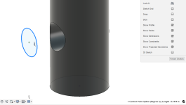
Or, in your case with Fusion, why is it that Fusion's CAM side ( assuming it does ) recognize the feature as a circle to be drilled or milled, and yet, the CAD side does not?
I know for a fact that the CAM side:
A) Does recognize the cylinder itself as an actual cylinder
B) If I was to create a toolpath from the projected geometry, the toolpath would indeed be an arc move:
2023-03-01_17h06_46.png

As for why the Projection is incorrect, I'm unsure, it's not something I ever considered. Thanks for showing me the fault!
Fortunately, I do know the people in AutoDesk I would need to talk to, so...off I go!

-EDIT-..and...question has been asked. I'll post back here when I get an answer one way or another. Who knows, it could be "uhh....cuz that's the way we've always done it"?
 
Last edited:
I know for a fact that the CAM side:
A) Does recognize the cylinder itself as an actual cylinder
B) If I was to create a toolpath from the projected geometry, the toolpath would indeed be an arc move:
View attachment 389173

As for why the Projection is incorrect, I'm unsure, it's not something I ever considered. Thanks for showing me the fault!
Fortunately, I do know the people in AutoDesk I would need to talk to, so...off I go!

-EDIT-..and...question has been asked. I'll post back here when I get an answer one way or another. Who knows, it could be "uhh....cuz that's the way we've always done it"?

If you were to chamfer the edge of the circle, it would need to be the spline for tool pathing though wouldn't it?
 
Yes, indeed, because it IS a spline (assuming I'm trying to deburr the top edge). However, if I was to machine the bore itself, using the top (or bottom) edge as the driving contour, it results in circular moves (turn on Smoothing to "Fit Arcs")


Back
Top