What's new
What's new

Death and Rebirth of a 10EE WARNING: Graphic Content - Viewer Discretion Advised

Marc M.

Aluminum
Joined
Apr 21, 2005
Location
Marshalltown, IA
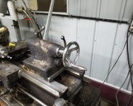
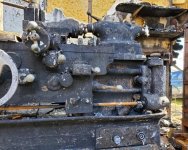
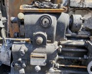
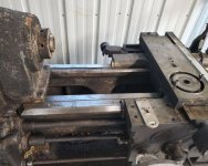
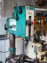
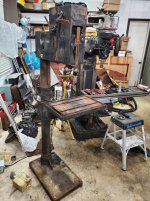
2 days prior to moving my equipment out of my Brother's shop and into mine it burned to the ground. I lost my Enco mill, Solberga drill press, and worst of all, my 10EE. All machines were in excellent condition, very little wear on them. It took me several years of hunting to come up with these machines, not to mention a fair bit of cash. His insurance would have covered everything so I contacted Monarch to request a quote on replacement. They said they could rebuild my machine and quoted around $63,000.00. Unfortunately my brother had lung cancer and died before the claims could be submitted. With no other recourse I drug my machine carcasses up to my place and set about repairing what I could. To add injury to insult, before he passed we were trying to get the machines moved. The Monarch slipped off a skate and while I was sticking it back under the machine, my brother slipped with the prybar resulting in the machine rolling over and crushing my left arm. Within a week he was pretty much paralyzed and I was left trying to move everything by myself with only 1 arm.

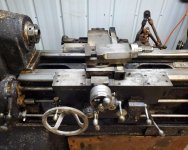
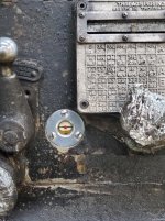
The Monarch is S/N 50294 manufactured 9-69. It has ELSR and a taper attachment. It came out of a Delco / Delphi plant in Ohio and was supposedly in an engineering modeling shop. There was a brass Delco ID tag affixed below the dataplate. The bed still had chips and misc. parts in it. I found copper, brass, aluminum, and steel chips. There was also a box in the end cabinet with a bunch of different odds and ends in it so the origin is plausible.

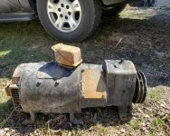
It had the original GE 5HP DC motor. The commutator and brushes looked like new, very little signs of wear on them. It was a modular machine but all the original electronics had been removed and an Allen Bradley 1395 DC drive retrofitted. The drive worked well although I couldn't get much over 3K RPM's out of it. I was running it off a RPC for several years without any problems until there was a brownout while it was running. It took out the main control board and I was having a problem finding a replacement for under $1200. To get it running until I could repair the drive I put a 5hp motor and VFD in it, direct drive, no back gear. I then saw Macona's AC Servo conversion and was immediately sold on it. I was able to snag a new in box Mitsubishi MR-H350A drive off Fleabay for $150 within a few months of looking. The motor was a different story. I wanted a 3.5Kw, 3K RPM servo motor, but most were only 2K. When a 3K would pop up it was hundreds, sometimes over $1000. It took about 3 years but I finally snagged one for under $200. Luckily I never had time to do the conversion and had all the servo stuff up here at the house so it was spared. The original motor and gear box were not so lucky and were in the garage when it burned down.
 

Attachments

  • 20190402_125745_sm.jpg
    20190402_125745_sm.jpg
    99.3 KB · Views: 387
  • 20190402_125742_sm.jpg
    20190402_125742_sm.jpg
    97.7 KB · Views: 334
  • 20190402_125736_sm.jpg
    20190402_125736_sm.jpg
    98.8 KB · Views: 367
  • 20190328_093901_sm.jpg
    20190328_093901_sm.jpg
    98.8 KB · Views: 330
  • 20190402_125732_sm.jpg
    20190402_125732_sm.jpg
    98.4 KB · Views: 310
Evaluation

I hired tow trucks at both ends to load/unload the lathe on a U-haul trailer. Both guys were great and were very careful getting it moved without doing any damage. At my house he was able to stick it fairly far into my shop minimizing the distance I had to move it with one arm. I just used a truck tire iron to lever it into place a half inch at a time. Once in place my priority was to get the rust off the ways, top of the carriage,cross slide, and dials. To protect my cast I would cover it with a plastic shopping bag then wrap it with plastic wrap several layers deep. Finally I would put a rubber glove on to keep my hand as clean as possible. My primary weapon to remove the rust/scale/soot was a fresh razor blade followed by Scotch-brite soaked in diesel to act as a lubricant, help break down the soot, and flush the debris. It took a lot of elbow grease but it worked well and I got everything cleaned up as best as I could. It was disheartening to see all the rust pitting and staining on what were pristine ways and the gorgeous stain dials. Fire is such a horrible event. The heat bakes all protective oils out of the metal then the fire department douses everything with water creating instant rust. It then takes the insurance company 2 weeks to get an adjuster out to inspect everything before you can start clearing stuff out and try to mitigate the damage. But that's the cards I was dealt so quit whining and get on with it. A quick check with a level and I wasn't detecting any twist in the bed so at least I had that going for me. I doused everything in oil to prevent further rust damage.

Most of the knobs melted, the few that were steel survived. The feed/threading data plate survived but the Feed/Threading plate that surrounds the selector knob right above it didn't. The apron handwheel survived with minor damage but the tailstock handwheel melted off. Some of the wipers turned into charcoal while others were in remarkably decent condition. Needless to say the Sony DRO and scales were toast as were my controls and wiring but fortunately the spindle interlock and ELSR microswitches all survived. The VFD that was inside the control cabinet didn't make it but the motor was OK.
 

Attachments

  • 20190402_140524_sm.jpg
    20190402_140524_sm.jpg
    99.4 KB · Views: 204
  • 20190516_171945_sm.jpg
    20190516_171945_sm.jpg
    94 KB · Views: 226
  • 20190516_222744_sm.jpg
    20190516_222744_sm.jpg
    93.8 KB · Views: 308
Once the ways were cleaned up my other priority was to get any oils and whatever water managed to find its way into the machine from the firemen's high pressure hoses. Certainly the quick change box would have water due to the selection window evaporating during the fire. But before I could do that I needed to replace the sight glasses as they had all turned into charcoal and were no longer keeping the oil contained. I sniffed around the net and couldn't find any used ones for sale. It was looking like I'd have to pester Monarch when I ran across the late Steve Bedair's excellent solution. He purchased screw-in sight glasses then machined them down and press fit them in the original aluminum housings. So I ordered some of the sight glasses and did just that. I cleaned and polished up the aluminum housings then pressed in the new plastic sight glasses, made up a new gasket and reinstalled it on the machine. They look great! I was then able to drain the headstock, gearbox, and apron and refill with fresh oil. That's about all I did to the Monarch last year. I still had my little Jet 9 x 20 that I could make round things if I needed, so my focus was on the mill and drill press.

I picked at both but getting the Solberga back up and running was the shortest path and I really needed a decent drill press. I contacted WIllis Machinery in Ohio who seem to be the main Solberga dealer in the US. This machine had their tag on it when I purchased it so I got in touch with them to see what parts were available. They were fantastic, very helpful and managed to come up with most of the parts I needed at very reasonable prices. The only parts they were having trouble with were the 2 switches. They really didn't know what they were and guessed they would be several hundred dollars each! The biggest concern was the motor as it is integrated into the casting and couldn't be substituted with anything else. Much to my surprise, the oddball Dahlander wound 2-speed motor turned out to be OK. I megged it and it checked OK but it looked rather crispy so I took it to a rewind shop for evaluation. They cleaned it up a bit, checked it, and said it was fine so I went with it. The most difficult and expensive parts to source were the 2 Kraus & Naimer switches. Between the tight integration into the machine and the odd switching arrangement the Dahlander windings required it wasn't going to be very easy to sub something different. It took a while but I was finally able to find enough bits on Fleabay to piece the electrical back together. I replaced a couple of bearings that felt a bit gritty and weren't wanting to clean up in the ultrasonic cleaner, again Fleabay to the rescue. Got it all back together, squirted some paint on it and it runs like a champ. So I managed to get 1 machine mostly done (still have to clean/paint the table and base). I was in the middle of getting the mill cleaned up and Bondo'd when winter came along and it was too cold to be dealing with Bondo as I don't have heat out in the shop.
 

Attachments

  • 20190606_191422.jpg
    20190606_191422.jpg
    92.8 KB · Views: 235
  • 20190416_081859.jpg
    20190416_081859.jpg
    99.7 KB · Views: 276
  • 20190524_185900.jpg
    20190524_185900.jpg
    99.5 KB · Views: 225
  • 20190524_154745.jpg
    20190524_154745.jpg
    74.4 KB · Views: 225
  • 20190516_172003.jpg
    20190516_172003.jpg
    96.1 KB · Views: 232
sorry to hear about all this misfortune. I'm sure you'll get things sorted with time.

Willis has always been helpful to me also.

BTW, I have 50292. Also 9/69. So, our machines were on the floor at the same time.

Dave
 
Sorry for all your loss, especially that of your brother. Truly amazing how far you have come with your machinery already. My 1968 10ee came out of Delphi also.
 
Sorry for your losses, but I admire your tenacity. Many would have left the machines for a scraper to take away. It looks like there's still hope for them!
 
Thanks for everyone's kind words. By far the loss of my brother was the worst aspect of all of this. He was my big brother and my inspiration from an early age for most of my pursuits in life. I've felt a bit lost since he passed since he was the only person I know that shared my interests in machining, mechanics, etc. and often served as my motivation to take on projects.

After a long, cold, depressing winter here in Iowa we finally got about a week of nice weather. I took full advantage and picked at the Monarch. I realized that I had the same size QD bushings on both the servo motor and 5hp motor that was in the Monarch so I could bolt the pulley right onto the servo motor. The servo motor is 3.5 Kw, a bit over 4.5 HP so I intend on using the back gear box. One of my stalling points on installing the servo prior to the fire was coming up with a splined shaft to fit the gear in the box. Since the original motor was burned up in the fire I went ahead and lopped off the motor shaft solving the spline issue. I'm going to use the original motor end bell as the adapter housing which will save a lot of work. But I need to get the lathe running to machine the shaft and adapter plates so I pulled the AC motor out and very crudely installed the servo motor. It's not very elegant, but it should be good enough to get the few bits I need machined.
20200403_181244_sm.jpg

I re-purposed a stand I stole out of scrap at work to mount the control cabinet to the original control cabinet mount. Like I had on the lathe originally, I mounted a piece of Unistrut across the top front face of the control cabinet to mount the controls and DRO and allow them to be easily moved around.
20200411_194637_sm.jpg

The control is based around a Mitsubishi MR-H350AN servo amplifier. For right now I'm running it in speed mode using a potentiometer to control the speed. Actually, I'm using 2 pots, one to set the forward speed and one to set the reverse speed allowing them to be controlled independently. I also wired in a % Power and an RPM meter I salvaged off a CNC control panel that was going in scrap and stuck them on the front panel. Tacked a trim pot on the back of each one to dial it in. In order to start the motor, 2 inputs need to be turned on. First the Servo ON input has to be connected, then a direction input and the motor will run. The caveat is that when the Servo ON input is connected, the drive "locks" the motor shaft by monitoring its position and energizing the motor in the opposite direction of an applied torque to maintain its original position. So when the lathe is stopped, the Servo ON input has to be disconnected so you can freely rotate the spindle. The Servo ON input has to be active in order for dynamic braking to work therefore you can't simply tie it directly to the apron control. To get around this a timer relay is used to hold the SON active for a set time after the control is turned off, in this case about a second. I went ahead and included a switch on the control panel to over-ride the spindle lock and a second switch to turn it ON or OFF. The drive also includes 2 inputs for limit switches that will shut the drive down if they are activated. I thought they might make an easy way to implement a truly electronic ELSR. So I also added 2 switches to enable the left and/or right limit switch and wired in 2 proximity switches. They are just standard prox. switches so I'm not sure how repeatable this setup will be but certainly good enough for general stops. Once everything is up and running I'll do some experiments to determine if they're good enough for threading to a shoulder.
IMG_5526_sm.jpg

I pulled the original spindle interlock and 3 ELSR microswitches off the lathe and brought them inside for cleaning and inspection. They all cleaned up pretty decently and I was happy to find that all of them had both NO and NC contacts. My servo drive was going to require slightly different logic than the original drive required so I was in good shape there. The contact resistance was OK on a couple and iffy on the other 2 so I sprayed some Deoxit in all of them. This cleaned them right up and I was now getting a solid contact on all of them.
20200403_141635_sm.jpg
I got them reinstalled on the machine but found the ELSR control knob wouldn't turn. I sprayed it down with Aerokroil and tried working it but didn't get anywhere. I could get a tiny bit of rotation out of it so I concluded the rod was probably free and the detent was probably frozen. So I pulled the set screw and spring out and sprayed Kroil down the hole. Took a small punch and tapped the plunger then worked the knob, rinse and repeat. Finally after a half hour of uttering expletives I got it to break free. The plunger was still stuck but at least I could rotate the knob. Now that everything was freed up, I wired up the ELSR switches using the original wiring. The ends had melted but there was plenty of slack so I just pulled it out to get to good wire. The spindle interlock wiring was toast so I had to run 2 new wires for it.
20200406_181955_sm.jpg
Once everything was hooked up, I applied power and brought her back to life. I was not disappointed with the performance, behaved just like Macona's did in his video's. Can't thank Jerry enough for the inspiration!
 
I don't know what others here do, but my 10EE sits on a pair of 4x4s, and I can move it with a pallet jack in case of need. Getting it into the shop I needed a big boom tow truck to lift it off my trailer and into the shop door.
 
Been back out in the shop the past couple of days. Found a local gas station that has kerosene for $4.25/gal so I picked up 5 gallons to run my old wick style kerosene heater. It keeps the shop in the mid 60's, warm enough for me to be able to work.

One of the things that really took a hit in the fire were the knobs as most melted. Sniffing around the net didn't reveal much in the way of replacements. I did find an A-B shift knob on Fleabay for $50+, seems like a lot but it was the worst of the lot on the lathe so I pulled the trigger. It's condition was disappointing. I didn't realize that it was a 2 piece knob, the knob is aluminum? while the skirt was steel. Oddly there was a lot of wear on the Fleabay knob skirt, the chrome plating was worn down thru the copper plate to the base metal. My skirt was in a lot better shape so I swapped them out. The other disappointing issue with the replacement knob is the A and B are not stamped very deeply and a bit difficult to read. I spent some time buffing the replacement knob and got it looking relatively decent.E-bay A-B Knob.jpg20200417_210236_sm.jpg

I was very surprised that the feed/threading data plate survived given all the damage to the knobs around it. The window had evaporated along with the paint, but there didn't seem to be any signs of melting anywhere.
20200408_214751_sm.jpg
I ordered some thin polycarbonate from McMaster-Carr to make up a new window. I also made up a new gasket. The plate itself was cleaned with Brake-clean, then carb. cleaner, and finally 99% alcohol using a stiff brush as the face is highly textured. I used Scotch-Brite to clean up the sides and top. A final rinse in alcohol then rattle can sprayed it with gloss black Rustoleum. I put it in the oven @ 250° for an hour to speed up the drying process and possibly make it more durable (the internet jury was hung on that last bit). I then used a sanding block and some 220 grit paper to take the paint off the high bits and reassembled it. I was very happy with the results.20200410_182259_sm.jpg
 

Attachments

  • 20200411_194606_sm.jpg
    20200411_194606_sm.jpg
    91.4 KB · Views: 187
The tailstock was in very sorry shape, for some reason it seemed to have been in a particularly hot spot. The handwheel was completely melted off just leaving stubs where the spokes were.
20190402_140608_sm.jpg

I tore down the quill assy. and cleaned everything up as best as I could. I use a brass wire brush in a bench grinder to clean up a lot of the more heavily rusted or melted on fire debris. The dial on the back of the spindle was badly rusted and although I try to avoid wire wheels on graduations I really had no choice here. What remained of the handwheel came off rather easily, but the dial assy. required additional persuasion. It uses 2 ball bearings and springs to provide the friction between the dial portion and the hub it rides on. Both those balls were heavily rusted and the springs were collapsed. I replaced the balls but couldn't scrounge up any suitable springs. I assumed the fire removed the temper from the springs but when I pulled them to spread them back apart they stayed and seemed to be sufficiently 'springy' so I put those back in. The wiper retention ring and the trim ring on the back side were cleaned up with diesel/Scotchbrite then buffed to make them shiny again. The quill was mostly retracted when the fire broke out, the protruding bit cleaned up nicely. The taper had some light rust in it. I used diesel soaked Scotchbrite stuck on a short shaft and slowly spun in an air drill to clean up the rear where my fingers couldn't reach. At some point down the road I'll blue it up and check for contact, but for now I can jam a chuck in there and it seems to hold fine. I made up a temporary 'handwheel' to make it usable until a more permanent solution could be implemented.
20200409_174611_sm.jpg

Again sniffing around the net didn't yield any tailstock handwheels for sale. I found one or two that had sold well over $100. As much as I liked the original handwheel with it's straight knurled ring, I just can't justify that kind of money so it was back to Fleabay. I found a 6" 'all metal' handwheel for around $15 and it came with a spinny handle (I prefer handles that spin) so I pulled the trigger. I figured it would be aluminum or some sort of pot metal but I was surprised to find it's presumably cast iron. It's pretty heavy and it took a bit of effort to push the broach thru to cut the keyway. I thought 6" might be a bit big but it seems to be about right. All in all I'm rather happy with it although I still would prefer the original one.
20200411_194606_sm.jpg

I also went ahead and pulled the apron off. I wanted to clean out any junk out of the bottom of the apron, clean the inlet to the pump, and make sure the pump was still pumping. Also, the whole time I had the lathe the forward reverse handle was incorrectly timed. When you would go down, you could just push it down, it didn't lock in neutral. When you would go up, it would lock in the up position requiring you to pull out the handle to return to neutral. So it was clear that the up position was where neutral should be and neutral was located where the down position should be. I knew I needed to move it a tooth in the gear train, I just wasn't sure how to go about that. Pulling the apron turned out to be a non-event. The taper pins came out of the shafts without much drama and the box wasn't as heavy as I had anticipated. With it off I was able to find the cap screws that were invisible due to paint, accumulated oil and grime and all the charring. The ELSR handle section is actually separate from the gearbox cover. Removing the ELSR section revealed the gear for the ELSR rod in the bottom half and the gear for the handle in the top half so correcting the improper timing was straightforward. On the gearbox side I did find some coagulated oil in the bottom cover, but all in all it was rather clean. I cleaned out the old oil and gave it a good rinse in Brakeclean. The filter looked good, no signs of any debris or fines in it. I rinsed it off with some ether and reassembled everything. I dumped some waylube in it and started cranking the handle. I cranked on it for quite a while and got nothing. Just when I was about to toss in the towel, low and behold some oil started appearing out of the port. It doesn't pump much at a time but it was pumping. I held my finger over it and cranked some more. When I let off I got a nice little spurt so It's building up some amount of pressure. Good enough for now, I figured I'd monitor the ways when I use it and make sure they are getting wet. It doesn't take that much to pull the apron so if there's an issue, I'll get some parts ordered and then pull it back apart. Upon reassembly I left the leadscrew out. It needs heavy cleaning but I don't want to tackle that until it's warm outside.
 
Next on the list was tackling the backgear box. It was out of the lathe with the motor so they bore the direct brunt of the fire. The most obvious issue with it was the oil sight glass was damaged and leaking. Unfortunately, unlike older versions that used a method similar to the headstock and apron, this version had a pressed in sight glass. According to the parts manual, the sight glass was not available as an individual part, you had to buy the entire casting with the glass already pressed in. Arrgghh. I pulled the casting to evaluate the damage, maybe I could get lucky.

20200412_151031_sm.jpg

Yeah, not a chance. It's real glass but it's now in multiple pieces. Now what? I broke the glass out of the housing. I could then get under the inside edges with a screwdriver and was able to slowly work the housing out of the casting.

20200412_154024_sm.jpg

I still had a few more of the sight glasses I purchased to repair the others so I decided I could machine up a new housing and press it into the existing casting. The replacement sight glasses came with 1/2"-14 straight pipe threads and a rubber gasket. Simple enough that even I might be able to make one. So I whittled one out of a chunk of aluminum but, of course, I couldn't find a straight pipe tap, Make it work - I just used a taper tap and tapped it a little deep until I could get the sight glass to fully seat - good enough for who it's for!

20200412_180458_sm.jpg

But I just wasn't happy with it. With the dark background it wouldn't be all that easy to see the oil level. I really liked the look of it with the original chrome background. So I stared at it sitting on the bench a bit until I finally figured out a path. I carefully cut the top 'ring' off the original housing so I was left with a frying pan shape. I then bored out the back of my sight glass housing for a press fit of the 'pan'. The passages for the oil were left pretty narrow due to the bottom of the bore so I grabbed a Dremel and carved them out. The sight glass also came down far enough to interfere so that was also relieved.
20200412_214357_sm.jpg

Once I was happy with it I carefully crimped the very back edges of the bore so there's no chance of the 'pan' backing out in the future and called it a day. Here's the final result:

20200412_214514_sm.jpg

It's not pressed into the casting yet, I'll wait until I get it in paint. Now I just have to figure out how to adapt the servo motor to the gearbox.
 
Loving this thread, thanks for sharing you EXTREME trials and struggles in life. My thoughts go out to you and yours with everything that has happened. I'm cheering for you on this effort and will be watching closely. My vote is to name this lathe the "phoenix 10ee".

Keep on keeping on and we appreciate your shares.

Brian
 
So the last major hurdle was what to do about mounting the servo motor to the backgear box. My thought was to use the existing end bell from the original DC motor. I intended on just using a spider type coupling between the motor and the shaft. If down the road I try to come up with a servo driven gearbox I can swap it out to a zero backlash type coupling. The endbell with the access plates for the original brushes would make an ideal setup to be able to access the coupler. The problem with this setup is I need a second bearing for the input shaft as there is only 1 single bearing in the gearbox. So looking at the inside of the end bell I realized that there are 4 locating tabs for the ID of the original brush plate that would have been machined at the same time as the bearing bore was so they should be perfectly concentric with the bearing.
20200417_121641_sm.jpg

So I machined a plate out of 3/4" aluminum that fit snugly inside of the 4 tabs. I counterbored a shallow pocket in the face to locate a bearing retainer that I would machine next.
20200416_211322_sm.jpg

I machined a bearing retainer to accept a 6205RS (52x25x15) bearing that matched what was in the gearbox. I picked up some motor quality bearings of Fleabay for cheap so might was well keep everything the same.
20200416_211340_sm.jpg

I assembled the backplate then measured the distance from the inner race of the gearbox bearing to the face of my plate. I then cut the original motor shaft down to 25mm leaving the shoulder that distance minus a bit from the shoulder of the original bearing. I put the new bearing on the shaft, stuck the shaft in and then bolted the retaining plate on.
20200417_172010_sm.jpg20200417_172022_sm.jpg

I'm very happy with the way this came out. The shaft has good support now and hopefully there's enough room in there to fit the coupler. I ordered a piece of 5/8" aluminum plate off Fleabay, but it's coming out of Michigan and the company has been closed due to Covid-19. They were supposed to reopen the 14th, but I still haven't heard from the seller. Once that gets in I'll get it cut down to fit the bell housing ring and start figuring out shaft distances. I might have to space the motor out further to make everything clear, we'll see.

While machining the shaft I played around with my prox. switch based TELSR (True Electronic Lead Screw Reverse). Initial results were looking very promising, running around 1200 RPM, out of a half dozen passes to a shoulder the carriage stopped within a range of 0 to 0.0007", I think 3 times it stopped right at 0 so it's looking pretty good. When I get some time I'll try to document it's performance at various speeds. I'll also post a schematic of the wiring when I get that done. Right now all I have is my original hand drawn notes which give a general idea of how it's wired, but a lot of detail is missing.
 
Your ability to scavenge useful parts at low cost is an eye-opener, for example.
I've been dumpster diving since I was a little kid. Couldn't afford to buy things when I was a kid so I'd pull stuff out of neighbors garbage then try to repair it. I got a lot of great stuff that way and learned many valuable skills as a result. Outside of the Mitsubishi servo specific items, everything else in this build was scavenged from scrap. I was fortunate enough to be working maintenance in a shop that didn't feel the need to destroy everything that went in the trash or prevent employees from scavenging. The biggest problem with this behavior is the tendency to become a pack-rat or 'hoarder' in today's parlance. It certainly doesn't tend to go over well with those who possess the playgrounds we like to visit on a regular basis though. Mine decided to open her playground to the public so she's no longer an issue, but my family is certainly going to curse me when I die!


ESPECIALLY if.. it turns out you don't really even need the reduction gearbox....
It was always my intent to adapt the backgear box. This servo motor isn't quite 5HP. I'm not sure how its low RPM torque compares to the original Monarch DC motor, to be honest I couldn't be bothered to try to find torque curves for both to figure it out. I'm guessing they're are probably similar and Monarch decided it needed a backgear so I should probably follow suit. I don't really do much that will probably ever require it, but it would bug the living crap out of my OCD if it wasn't hooked up. It's bugging me now that the original speed control knob (well what's left of it) no longer has a function, but it doesn't outweigh the convenience of having independent forward and reverse speeds so I just deal with it.


Could was there is more present-day available expertise about them than either of OEM DC or the VFD conversions?
I'm sorry, not sure where you were going here??
 
It just occurred to me that the Mitsubish MR-H350AN drive that I used for this is NOT rated for single phase use, 3-phase only. I put this together at least 10 years ago so I've forgotten many of the details but I thought this was important and that I should mention it. I think I replaced the input rectifier module with a slightly beefier unit since all the current will have to go thru 2 diodes instead of 3. I also added some capacitance to the DC buss to help keep it from dropping because there is a lot more 'dead time' between peaks on a single phase waveform vs a 3 phase waveform. Prior to the modifications I took it into work and monitored the DC buss voltage with it running off of 3-phase power and loading the motor as best I could. I repeated the process running it off single phase after the modifications and the DC buss voltage actually drooped slightly less so I called it good. I'm not an EE, I often have trouble working a wire-tie so I don't know if what I did was right or a good idea, there are some way more knowledgeable folks on here that may be able to chime in. All I can say is so far, so good and it's something to keep in mind when looking at servo drives.
 
Updates please? Your rebuild is very inspiring. I'm doing my own 10ee rebuild as well, although mine was not fire damaged.


Back
Top