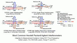
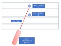
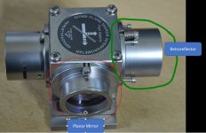
A few months ago I purchased Laser Interferometer DIY kit off ebay to help tune by Fadal Ballscrews since I was unable to find a cheap check master gage. I would have bought a new ballscrew but everyone has been out of metric 4020 Y-axis ball screws till Oct. The seller Sam was very responsive to questions and fine tuning the kit to my needs. This will be a Interferometer using a Two-frequency laser setup.
Requirements
1. Ability to upgrade the system to multiple axis down the road
2. Enough power to measure a Fadal 8030 for a buddy.
In short order he had a system listed on ebay with a high power laser and 9mm beam size for a decent price of $1,430 with 2 day shipping. I was itching for something to do over the 4 day weekend. Kit uses a HP 5517C that has been verified to work and repaired if needed.
https://www.ebay.com/itm/303500535042?hash=item46aa0aa502:g:9r4AAOSwsTxgQ-Wt

Instruction manuals for kit
https://www.repairfaq.org/sam/manuals/hobspcl1.htm
Bag of parts and one laser.
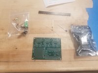
Not a real difficult system to solder together. You will need a fine tip soldering iron and some patience. I only purchased the board parts for 1 axis but the remaining axis's would be cheap.
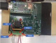
The next part caused me about 1.5 days of frustration trying to get the system running. After soldering the board together I accidentally wiped the firmware on the controller board when doing a power on test and had to reloaded the file. Sam had everything posted on his website for the firmware and instructions how to load it. Reloaded the file just fine but I was unable to get the system running after aligning the lasers. I'll give Sam credit for the quick responses about the problem. We exchanged over 35 emails in the last two days trying to figure out what the problem was. Multiple signal checks using a DMM and Oscilloscope resulted in us scratching our heads. In the end we found the firmware on the website was corrupt and he was able to send a working one over. Guess I was the first to blow away the preloaded firmware. He has uploaded the correct one to the website now. Gold Star to me
I've uploaded some pictures of the test setup. The hydraulic table is limiting my ability to get everything level and adjusted perfectly. Now that I have the system running I will be purchasing some additional hardware to make the setup easier. I was able to set the backlash on the middle and positive end of the Y axis but need to adjust hydraulic table before completing full motion.
Initially playing with the setup.

Current setup. I machined a custom fixture plate to mount everything down to.

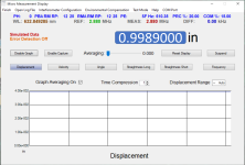
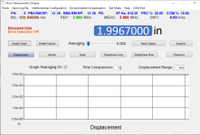
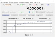
Screen shot from program.
Items to buy to improve setup
Accuracy of the system should be no issue as the display shows. I only somewhat under the principles behind the science but overall the system will have no issues measuring .00001. Even rolling my chair near the setup causes a change in measurement. I believe the accurany was around 6 nano meters which is about 0.00000023622 inches. I will need to verify the exact number.
Few extra links for learning
Renishaw XL10 page
https://www.renishaw.com/en/interferometry-explained--7854
Sam's link. Way above my head for most things. Massive archive of laser info.
https://www.repairfaq.org/sam/laserfaq.htm#faqtoc
I will add more info tomorrow.
Requirements
1. Ability to upgrade the system to multiple axis down the road
2. Enough power to measure a Fadal 8030 for a buddy.
In short order he had a system listed on ebay with a high power laser and 9mm beam size for a decent price of $1,430 with 2 day shipping. I was itching for something to do over the 4 day weekend. Kit uses a HP 5517C that has been verified to work and repaired if needed.
https://www.ebay.com/itm/303500535042?hash=item46aa0aa502:g:9r4AAOSwsTxgQ-Wt

Instruction manuals for kit
https://www.repairfaq.org/sam/manuals/hobspcl1.htm
Bag of parts and one laser.

Not a real difficult system to solder together. You will need a fine tip soldering iron and some patience. I only purchased the board parts for 1 axis but the remaining axis's would be cheap.

The next part caused me about 1.5 days of frustration trying to get the system running. After soldering the board together I accidentally wiped the firmware on the controller board when doing a power on test and had to reloaded the file. Sam had everything posted on his website for the firmware and instructions how to load it. Reloaded the file just fine but I was unable to get the system running after aligning the lasers. I'll give Sam credit for the quick responses about the problem. We exchanged over 35 emails in the last two days trying to figure out what the problem was. Multiple signal checks using a DMM and Oscilloscope resulted in us scratching our heads. In the end we found the firmware on the website was corrupt and he was able to send a working one over. Guess I was the first to blow away the preloaded firmware. He has uploaded the correct one to the website now. Gold Star to me
I've uploaded some pictures of the test setup. The hydraulic table is limiting my ability to get everything level and adjusted perfectly. Now that I have the system running I will be purchasing some additional hardware to make the setup easier. I was able to set the backlash on the middle and positive end of the Y axis but need to adjust hydraulic table before completing full motion.
Initially playing with the setup.

Current setup. I machined a custom fixture plate to mount everything down to.

Screen shot from program.

Items to buy to improve setup
- Rigid tripod
- Foam for my pelican case.
- Lab jack or build a mount for the laser interferometer mirror.
Accuracy of the system should be no issue as the display shows. I only somewhat under the principles behind the science but overall the system will have no issues measuring .00001. Even rolling my chair near the setup causes a change in measurement. I believe the accurany was around 6 nano meters which is about 0.00000023622 inches. I will need to verify the exact number.
Few extra links for learning
Renishaw XL10 page
https://www.renishaw.com/en/interferometry-explained--7854
Sam's link. Way above my head for most things. Massive archive of laser info.
https://www.repairfaq.org/sam/laserfaq.htm#faqtoc
I will add more info tomorrow.


 I studied physics for my undergraduate degree and have always liked lasers and optics but thought interferometers were just far out of budget.