Melchizidek
Plastic
- Joined
- Dec 14, 2022
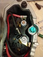
I purchased a Dayton Model 5K283BE 1/2 hp split phase motor for my SB 9A lathe. I needed to replace the old drum switch and purchased a Relay and Control Corp model RS-1A reversing drum switch from McMaster-Carr.
I have looked through many of the threads here and can't seem to understand why some wiring diagrams will show switch terminals #3 and #5 with a jumper and others do not. I think I understand how to wire the switch to the motor, but the jumper question has me stumped.
Why does #3 and #5 need a jumper?