What's new
What's new

Fanuc 6T Nakamura TMC2 (lathe)

davidwenrich

Aluminum
Joined
Oct 27, 2015
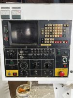
I have been working on this machine for quite some time, but I have been making progress. I can now write and execute a program. Movement and tool change commands work. The problem I am battling now is no spindle speed control via NC. Analog controls work spindle speeds fine. (I assume a potentiometer) When spindle is commanded on, it starts to turn, spins up to around 300ish RPM and then immediately goes to around 52-53 RPM and holds steady until dwell time in program is complete, then stops, reverses as commanded and does the same in reverse. I have manually altered input bits at the DAC on the spindle control board, and if a bit is pulled low the RPM increases as I assume it should.(all high when spindle turning at aforementioned 52-53 rpm, which should be zero RPM if I’m not mistaken) I had to change parameters here and there, and replace main PCB for controller to get this far. Z axis was only moving 1/2 the indicated distance (as if it were X in diameter) Changed Pulse multiplier parameter for that axis. Now position displays correct distance within .002” over 25.4 mm (I don’t have a metric long travel indicator) Main PCB changed to fix a no movement at all problem. The spindle speed problem has me stumps though. RPM is displayed correctly on the command screen I.e. 50 is 50, 1000 is 1000 when commanded from analog knob. Can anyone tell me about the tacho/generator/orientation pulse operation? Maybe position cannot be determined so it will not spin up? Makes no sense to me that rpm is incorrect, but program runs with no alarms/errors.
 

Attachments

  • F66D5C3A-B343-4945-8BE0-F123AE701544.jpeg
    F66D5C3A-B343-4945-8BE0-F123AE701544.jpeg
    1.8 MB · Views: 17
  • B0245C50-2328-4050-916D-11A4A8704DFF.jpeg
    B0245C50-2328-4050-916D-11A4A8704DFF.jpeg
    1.8 MB · Views: 15
  • 86FA3A47-D715-4211-A66E-A41FA018EEDB.jpeg
    86FA3A47-D715-4211-A66E-A41FA018EEDB.jpeg
    1.4 MB · Views: 17
Hello David,
You're starting the spindle in G96 (CSS) mode. The actual revs of the spindle will be determined by the diameter the control thinks it at. You have a Reference Return Command, but no G50 to set the Work Coordinate System, so the diameter the control thinks its at could be anything.

After selecting an appropriate gear, try G97 S500 M03. That should give you a spindle rev of 500 RPM.

G50 is also used to clamp the maximum spindle revs when Constant Surface Speed Mode (CSS) is being used. Starting the spindle in CSS before setting the Work Coordinate System and the Maximum Spindle Revs can be dangerous. Without setting the Work Coordinate System, the Absolute Position Readout could be anything and if it were to be a very small diameter, then the control will try and achieve the high RPM to satisfy the programmed CSS, in your program example of either 1000 feet per minute, or 1000 Metres per minute. Practically any CSS programmed will equate to very high RPM if the Absolute Position display is small and no Maximum RPM limit has been set with G50.

Regards,

Bill
 
Last edited:
Hello David,
You're starting the spindle in G96 (CSS) mode. The actual revs of the spindle will be determined by the diameter the control thinks it at. You have a Reference Return Command, but no G50 to set the Work Coordinate System, so the diameter the control thinks its at could be anything.

After selecting an appropriate gear, try G97 S500 M03. That should give you a spindle rev of 500 RPM.

G50 is also used to clamp the maximum spindle revs when Constant Surface Speed Mode (CSS) is being used. Starting the spindle in CSS before setting the Work Coordinate System and the Maximum Spindle Revs can be dangerous. Without setting the Work Coordinate System, the Absolute Position Readout could be anything and if it were to be a very small diameter, then the control will try and achieve the high RPM to satisfy the programmed CSS, in your program example of either 1000 feet per minute, or 1000 Metres per minute. Practically any CSS programmed will equate to very high RPM if the Absolute Position display is small and no Maximum RPM limit has been set with G50.

Regards,

Bill
Tried as you Suggested. Same result. I have tried several iterations of G97 and G96, as well as limiting spindle speed. The only time it ever spun up was when I commanded gear change, it seemed to run away and was trying to grind back into gear. E-stopped immediately (I always hover over it because I don’t really know what I’m doing yet) checked parameter for max speed during shift, is/was set to 50 RPM. Have already checked range switches. They are working.
 
Post a picture of your drive. While some machines are configured to use the DAC, it is also very common to use a 0-10 velocity command from the CNC. I’m wondering if in all your parts swapping the correct setup is not being used.
 
Thank you for your reply. I have fixed the problem, The machine is now operating as intended. (As far as I know.) So far all problems I have had have been due to incorrect parameter settings, except the no movement// bad PCB. All parts replaced with exact part number/ rev version, or approved/suggested by Fanuc USA. Parameter 010, bit 4 spindle stop signal switch NO/NC switched bit from 0 to 1, Now reads 00010000, spindle responds as it should. Have to get offsets loaded to check G96 now. Will be checking all parameters that I can, bit by bit, to make sure they make sense. a lot of variables to deal with. The parameter settings I got from Methods Machine (US Nakamura Dealer) are not 100% correct. Some are not legible at all. A lot of help though. Both Methods Machine and Fanuc USA have been very helpful. Great support. The Fanuc 6T maintenance manual I have is not 100% correct either for my machine. Some diagnostic bits are in different groups than expected, i.e. pendant spindle start/stop bits being on diag 037-038 and not on 032-033 for example. (This is just an example of the situation, not actual location) It's slowly coming together though, made my first programmed facing cut before I left the shop today. No offsets. just using X-Z relative to machine 0,0... Proud I got that done.

Thank you,
David
 
Have to get offsets loaded to check G96 now.
Your machine doesn't use Geometry Offsets for the Tools, or Work-shift Offsets to establish a Work Coordinate System. Although some current users of the old 6T control use large offset as tool offsets, you have to be careful, as the Offset is taken up as an actual movement when the Tool Offset is called. Also, if you call the Tool Offset at the same time as the Tool is called, the movement occurs as the Tool is indexed to position and can be a rather off putting. Accordingly, it's better to call the Tool first and then apply the Tool Offset during the first movement command, as shown following:

G28 U0.0 W0.0
G50 X400.000 Z500.000
G00 T0100 G50 S2500
G96 S250 M03
G00 X200.000 Z10.000 T0101 M08

The FS6T Control was meant to use G50 to set the Work Coordinate System for each tool using G50, as in the example above. From a known, repeatable position, such as the Reference Return position, G50 is specified with X/Z coordinates that represent the distance from the X/Z Zero of the Workpiece to the Tool at the location where the G50 is used to set the Work Coordinate System. Offsets then are generally just small wear offsets.

Regards,

Bill
 
Thank you Bill. Although I am not fluent, I am at least aware of that "quirk"?? for lack of better word. I have read about peoples work around, but i would like it to function as the manufacturer intended, as I intend to hopefully use a post processor specifically coded for this machine. Don't want to waste a large sum of money on a post that I have to edit.
 
Thank you Bill. Although I am not fluent, I am at least aware of that "quirk"?? for lack of better word. I have read about peoples work around, but i would like it to function as the manufacturer intended, as I intend to hopefully use a post processor specifically coded for this machine. Don't want to waste a large sum of money on a post that I have to edit.
And I don't want to use the only other offset available, besides the G50,as primary tool offset.
 
On your lathe, do you have to input an M42 command before you can enter the spindle speed and direction in mdi to get it to spin up? Took me an hour messing with mine to figure that out.
 
Your machine doesn't use Geometry Offsets for the Tools, or Work-shift Offsets to establish a Work Coordinate System. Although some current users of the old 6T control use large offset as tool offsets, you have to be careful, as the Offset is taken up as an actual movement when the Tool Offset is called. Also, if you call the Tool Offset at the same time as the Tool is called, the movement occurs as the Tool is indexed to position and can be a rather off putting. Accordingly, it's better to call the Tool first and then apply the Tool Offset during the first movement command, as shown following:

G28 U0.0 W0.0
G50 X400.000 Z500.000
G00 T0100 G50 S2500
G96 S250 M03
G00 X200.000 Z10.000 T0101 M08

The FS6T Control was meant to use G50 to set the Work Coordinate System for each tool using G50, as in the example above. From a known, repeatable position, such as the Reference Return position, G50 is specified with X/Z coordinates that represent the distance from the X/Z Zero of the Workpiece to the Tool at the location where the G50 is used to set the Work Coordinate System. Offsets then are generally just small wear offsets.

Regards,

Bill
Hi Bill,

Please tell me if I'm understanding the intended workflow for setting tools on the 6T:

1. load program
2. touch off tool/take skim cut
3. write down the X centerline and Z zero location as referenced from a fixed position(machine home/return)
4. manually input those written numbers into the program where the G50 calls the x0 y0
5. run program...carefully.
When setting a number of tools,
1. At the location where the G50 will be executed for each tool, Zero the Z position display and register the diameter of the OD (for setting OD Tools) or the ID (for setting ID Tools) in the X position display as a negative of the measured value. For registering X, this can be done by either executing G50 and the X address value via MDI, or turn Machine Lock on then use the Hand Wheel to register the required value. Turn Machine Lock off when done.
2. Move each tool to be set to touch off on the cut diameter and Z Zero of the work-piece. The G50 for the Tool being set will be the Absolute Values of the displayed values (which will be negative values)
3. Repeat step 2 for other tools to be set. If you have to change from setting OD to setting ID tools, or visa versa, change the registered X value to the negative value of the alternate surface (OD or ID surface).
4. Write the obtained G50 values for all tools being set and used in the machining operations, into the program.

Regards,

Bill


Back
Top