What's new
What's new

Fanuc Modes- Auto, MDI, JOG etc OMD

I replied to your PM with some info about the 900 parameter lists you sent me. Have you had a chance to look at the info and one question? Since the forum moderator asks that option and configuration parameters not be publicly posted some of the info is best discussed by PM. Other things like my question asking if you have a board plugged into the slot labeled PMC on the mainboard is fair game on the open forum.
 
My machine is 2002. I have a the full printout of parameters that came with the machine and it has a matching serial number. The printed manuals show the 900 parameters but this is dated, 2000. There are some differences.

There may be a soft options to change modes, but my hard option does not work and it should.
 

Attachments

  • Special_2000_2002.pdf
    12 KB · Views: 11
My 900 data. The only G-Code machine I have is an Anilam Lathe. Very simple and works well. (Competely rewrote the ladder in the Mitsubishi controller as the tool changer kept faulting. Also added outputs for my DIY pnumatic bar feeder)

My CNC mill is conversational only. It has a South Western Industries controller.
I've had it for 20 years and works nearly every day. I wrote some software for it and I can now take a DXF - convert to G-code with sheetcam, and I interpret the Gcode into conversational and then convert to HEX for my controller. I did that by reverse engineering the operations, made one change, see what changed in the hex, made another etc etc . It works so well I never upgraded to a full CNC. It only has a semi automatic tool changer. The YANG purchase with the 12 post auto toolchanger was the draw card.

So I'm new to Fanuc CNC and I may be completely off with my reasoning but I'll get there.

See here for a video

Yang Video
 

Attachments

  • 900.JPG
    900.JPG
    45.9 KB · Views: 5
  • 920.JPG
    920.JPG
    51.1 KB · Views: 4
Last edited:
Oops, I replaced the eproms this morning and all was well. After a few boots I got the attached.

I accidentally bent one eprom pin. Must have worked for a while.

Reseated the eprom but no joy. I've found a burner near me and some M27C256B. Hopefully, burn the new ones and fix the issue. Lucky I read them all yesterday.

I'll the report back. Must be home time for you.
 

Attachments

  • Boot.JPG
    Boot.JPG
    12.7 KB · Views: 1
The gods were with me today. After a bit of reading and making a parallel cable, I got the Willem 5.0 programmer I was given to work with 2nd hand blank chips and I now have nice fresh eproms and the machine boots correctly. I dodged a bullet.

I'll report back on the memory contents tomorrow. Near my bed time.

.
 
I booted the machine several times today and 1st time I was in EDIT, second AUTO and third JOG. Each time I rebooted after that, I was always in JOG.

Leaving the machine off for 20 minutes, the boot came back to EDIT. I have had MDI come up in the past, so completely random.

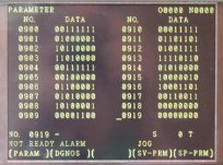
None of the values changed during this process.
The buttons all set the appropriate LEDs on the console but did not change the any of the registers below.
X021 00001000
G104 00000000
G121 00101110

However some new advancement on this. I have a button on the console that says EM - The manual says," Press this button to release the EM alarm if over-travel. And choose any axis direction would do the feed motion of any axis. "

When I press this button with the E-Stop out, A contractor comes in and on releasing I get error 434 and the buzzer - The servo drive comes up with A -> Z axis error.

This could mean that under a fault conditions, a lot of 'normal' things are disabled like the mode options.

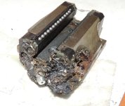
It is a long shot, but was wondering if the Z Axis brake could be stuck.
 
21.4 and 121.4 both should be 1 for normal operation. 21.4 is the physical e-stop circuit and 121.4 is e-stop from the PMC to the CNC.

For the 434 alarm post the contents of Diagnostics 720-723. These detail the servo alarms.
 
I'm beginning to believe that they made an effort to get the machine to run but not too much on data when things go wrong. There are no X+ X- etc limit switch inputs to the controller. They appear to be all strung together into an e-stop loop or something like that.

X024 -> 11111111
G121 -> 00101110

G121.4 is E Stop

*720 - * 723 all zero. (Called * for some reason)

(I don't have any printed data on registers above R654 or X022)

Now if I press EM with the e-stop out, the 3 phase main contactor comes in and KA1 activates which provides 24VDC A. G121.4 gets set and after a few seconds the contactor and relay drops and out I get Error 401 VRDY off and 434 Z Axis. Once I let go 401 drops away and I only have 434. G121.4 is no longer set.

Now *722 -> 00010000

The contactor will not come in again till I power off the whole machine, but the KA1 still does when I press EM.
 
Last edited:
Found this post (Not to sure how to post the link)

0M-C ERROR 434, Diagnostic 722, What's the answer?​

High current - could it be the brake sticking ?
 
722 is showing a high current alarm on the Z axis. Some common things that cause that alarm.
Short in the motor. Disconnect power connector. Meter leg to leg and legs to ground. Leg to leg should be low resistance like around an ohm. Legs to ground should be megohms to infinity.

Short in the motor power cable or connectors. disconnect from drive and motor. Meter leg to leg and leg to ground. All should be megohms to infinity.

Bad transistor module in the drive. Usually a short between C-E on the module.
 
Found this post (Not to sure how to post the link)

0M-C ERROR 434, Diagnostic 722, What's the answer?​

High current - could it be the brake sticking ?
Only if the alarm takes a while to turn on. In most cases the motor is plenty powerful to overcome the brake without going into high current. If the alarm comes on quickly or instantly it's more likely one of the issues I listed earlier.
 
.....There are no X+ X- etc limit switch inputs to the controller. They appear to be all strung together into an e-stop loop or something like that.
That is a pretty common handling for hard overtravel. There are software limit parameters in the control. When those are properly set you should not trigger a hard overtravel/e-stop limit switch.
 
I measured the motor and it is 1.5 ohms per phase. When pressing the EM, I am seeing some Z movement before it trips out.

Never having run the machine before, does it home when started? I doubt it, that would be dangerous.

I'll have to see why I'm getting a Not Ready signal. I don't have a full wiring diagram and I don't have 24VDC-A unless KA1 is in. Really not sure why its not in when power is on. Maybe it is the E-stop power circuit ?

I'll have look tomorrow.
 
How much movement? A mm, cm?

The machine will not automatically try to home at power on.

Not having a wiring diagram will be a major impediment to getting this running.

You have to find what physical device is keeping the physical E-stop circuit open (dgn 21.4). The E stop circuit is a NC circuit. Opening the circuit creates the E-stop condition.
 
Success in the E-Stop

I have some wiring diagrams and I have the part I needed.

Top rung. There is a bypass switch and this is the EM button I spoke about. It is SBP40. Quite a neat feature to have.

Checking the wiring, I found the Z limit switch faulty.

Now on power on, I wait a few seconds, no alarm and the main contactor comes in. I then get 401 and 434. The Z has moved a few mm.

Now that it appears to be all working, I'm at the position now where I want to remove Z column and service it. I would like to have the Z ballscrew free of the column before any more testing. Need to service all the rails and ballscrews before continuing.
 

Attachments

  • Wiring_1.JPG
    Wiring_1.JPG
    99.3 KB · Views: 4
  • Console.JPG
    Console.JPG
    138.2 KB · Views: 3
When I got the machine, the channels below the covers were full of swarf. Ballscrews and rails were soaked in rubbish. The X and Y bits the lube pipes were all off the blocks. Hadn't been greased for years. Se below. I replaced all the balls in both pillow blocks and ballscrews and it all feels nice and tight now. Modified the ballscrew lube point and the nipples for the pillowblocks. I turned down the nipples to give the pipe better purchase. Also added lock wire. The problem with this is the grease gun produces 1000's of PSI pressure and its so easy to blow the pipe off the nipple.

It was at this point I powered on the machine and had the Not ready message and then a month of chasing my tail to find the fault. Thanks for the help. It is not not all lost as I really know the machine well now and makes way for adding a 4th axis in the future. All the buttons and ladder appear to be there for it. I only make small parts so this machine is great.
 

Attachments

  • Ballscrew_Lube.JPG
    Ballscrew_Lube.JPG
    55 KB · Views: 6
  • Pillow_Grease.jpg
    Pillow_Grease.jpg
    52.1 KB · Views: 6
  • Wired.JPG
    Wired.JPG
    50.6 KB · Views: 6
  • Nipples.JPG
    Nipples.JPG
    6.7 KB · Views: 6


Back
Top