solidworks4u
Aluminum
- Joined
- Apr 23, 2011
- Location
- 19970 DE USA
13engines, thank you! I have a way forward with BobCad and Editor Predator to make a big part of the code ready to get the tool & program to become aligned to the start point that the machine agrees with.
The way it makes sense (because this I saw on YouTube) to me is start at the top surface of the mill table, z=0.0, I will allow for the vise height (with part included), unless this (at top of the part) is a better/preferred height to use as a start point.
The vise will have a stop to locate a sub-base to it each time in the same place, the sub-base will have a reamed hole to "Dial In" the x & y-axis. The small reamed hole will be located off the part, so I can check the starting point with an indicator with a part in place. The small reamed hole is at a known location in relation to the part's datum points.
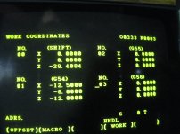
I will try to attach a few pics of the screen as I attempt to set the z axis with a "pin of known length" (see the 7.150" in top of pic 74). This is after "zero return" the pics are in order. Referencing, the last number of each pic; ends in 71 is the work coordinates; pic 73 is after "zero return" for all axis; pic 74 is when I put a 7.150" tall pin on machine table, this screen is after moving all the axis from the zero return locations, so I can get close to the pin in the center of table.I know that I am to use this 7.150" (181.615 mm) with the z axis number from "work coordinates" to set the top left spot in the "tool offset" screen, or have I mixed that up and need to go to actual position screen. You see in pic 74 "machine" (lower left on screen) is in metric, all others appear in inch (I do not know what happen). I am not clear in this part, but realize this is the area that will require to be edited often, so I need to be clear in my thinking.
I am not shore of my thinking, I need a second opinion, am I on the correct path?
Many, many thanks to you 13engines, and all the others who have been so kind to help!