What's new
What's new

fp2 table overhaul

Thanos, it is a good idea, I will check.

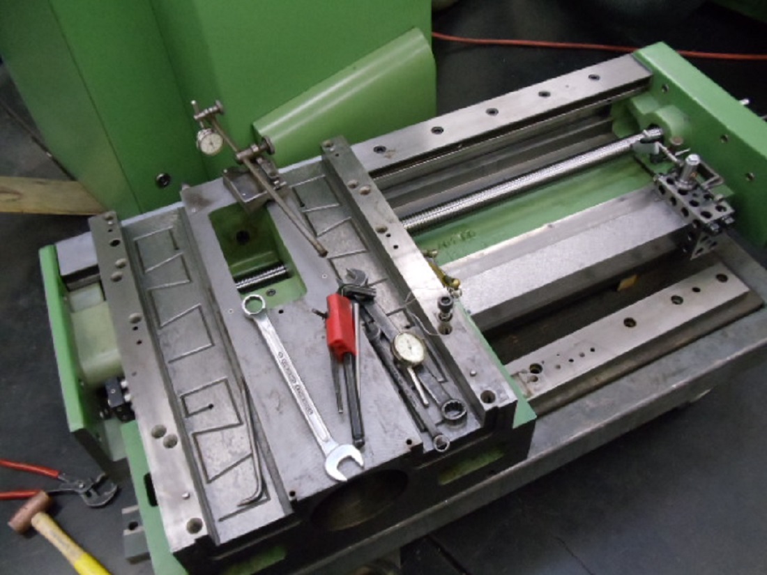
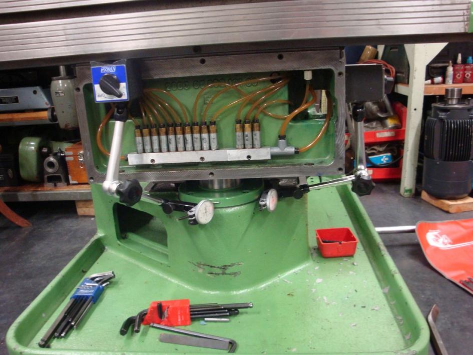
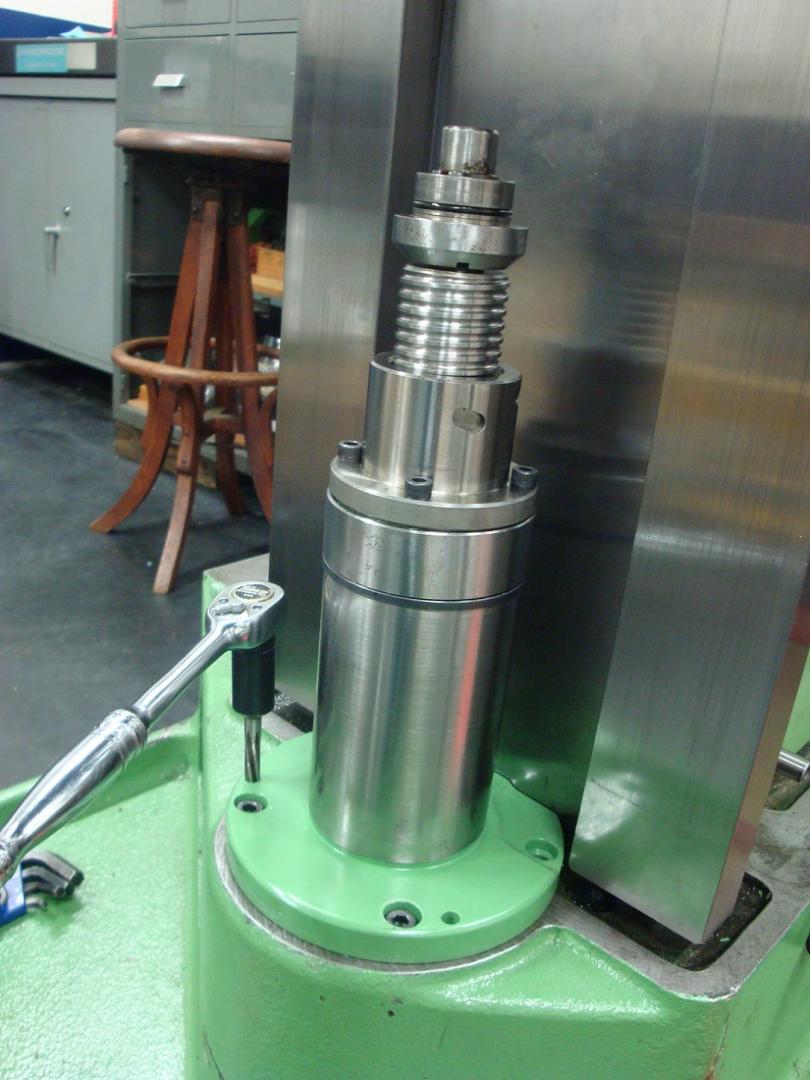
Since I posted above, I have scraped the Z axis gib flat. It took a lot of work, it had a lot of wear at the thinner end. It is not completely done (no attempt at spotting or flaking), because I decided it would make more sense to finish the scraping once the knee is back on the machine. I also scraped both of the X axis gibs, and will finish those when the X slide goes on. I measured the depth of the box ways and plan to have the keeper plates ground to match. Before I can re-install the knee, I need to disassemble and clean/de-grease the knee internal oil passages and the X and Z stop shifting linkage, similar to the work shown in Bruce Allen's thread: https://www.practicalmachinist.com/...-and-support-tear-down-and-reassembly.277534/

IMG_1345.jpeg
 
Last edited:
Thanks for taking us along the ride mate, geometrical reconditioning of machines fascinate me, keep up the nice work!

One thing that 'bothers' me when thinking about such tasks is screw alignment. After scraping things move a bit, what will you do to compensate for that?

Cheers
Thanos
 
Locating points for lead screws should be corrected when the slides move due to material removal/addition (Turcite)
The quick solution is to position the slide with the nut close to the support (bearing housing) and allowed to "float" within the clearance of the mounting bolts without any dowels or taper pins.
The bearing and the casting that carries the bearing move to get into alignment to the nut and ease the misalignment and angularity. For some this is sufficient and rely on the tension of the assembly bolts to hold position.
The process is repeated for each end bearing ("X" slide).
Personally i prefer to test alignment using indicators gauged off the sliding surfaces or fixtured on a surface plate. Then reworking the dowels or taper pins to hold position..

Here is one example, machine is FP3NC during slide rework.
Viewed with vertical slide face down, "X" axis screw in view.
full


Indicating surface is the slide, indicating on the OD of the ball screw.

full

Screw is carried by the end casting. Dowelled by taper pins (removed to allow the movement of the plate)

Once position is set, the taper pins were re reamed and oversized pins fitted.

full


Process was repeated on the opposite end after moving the slide to the opposite end of travel.

Cheers Ross
 
The vertical screw is different as for a Deckel its impossible to see both ends of the screw to gauge alignment..
Here the best one can do is to bring the vertical slide (nut) as close to the bearing at the base of the machine.
Here is my solution to getting the screw aligned as used on the same machine as above (FP3NC)

full


What you see here is the vertical slide (w lube checks) moved almost all the way down.
Lower in the photo is the base of the elevating screw flange (Green)
Here i have placed two indicators that bear on the flange at 90* apart.
The mounting bolts are loose and the locating taper pins are removed.

full


Longer shot of the setup.
Here i can move the screw to feel the play in two planes and using the indicated movement i can centralize the screw and tighten the bolts at the optimal position..

full


With bolts tightened (shortened Allen wrench), the slide is removed (lifted off the screw) to get clearance. Then the taper pin bores are reamed oversize to get good contact and
secure the screw location....

full


Cheers Ross
 
Hey Ross,

thanks for the elaboration, process it well understood. Thanks for the oversize taper pin tip, easy enough to do that does not make sense to leave each locating block not pinned.

Would you please also comment on my previous post on the reference surfaces for checking alignment on the Z slide? Especially for the latest generation manual 2/3s where the internal faces of the Z ways are the functional ones, it should be pretty easy to check alignment off the left (none gibbed) face of the Z slide: if the non-functional face is also nicely machined it should very handy.

BR,
Thanos
 
Last edited:
Thanos, I wrote a long note responding to your question. Thought I had submitted it, but the computer crashed, so it is gone. One thing I remember saying was to look in Bruce's thread linked above. He ran into the Z axis alignment issue even though he had not scraped any slides. His solution was to loosen the screws while the knee was at the bottom of travel, to let the screw self-align, then re-tighten. Maybe in a case where a lot of metal has been removed and no turcite applied to restore the original geometry, the mounting holes would need to be elongated and the housing re-pinned. Gear mesh is also an issue.

For the Y slide, there was enough wear that I applied turcite to the top of the column. However, the gib has not been fitted, it will be the last step. For the X slide, the slide ways have been scraped on the knee, but not on the x slide itself, that remains to be done. The X slide gibs have been rough scraped, and I will do the final fitting when I get to that point.

In the mean time my progress is slightly delayed. I need a way to lift the knee in position to check the alignment and fit. I thought about bringing in the shop crane, but there really is no room for it in my 16x16 shop with an FP2NC, a lathe and the FP2, not to mention workbench and cabinets. Its tight. So my project has turned into building a small wall-mounted jib crane. When that is done I will be back to working on the knee.
Hey there,

sorry to hear that you lost your post, really frustrating when that happens. (I always 'select-all' and 'copy' as a matter of habit before I hit 'post reply' in case the browser crashes).

How did you remove so much off the Y slide on top of the column so as turcite has space to fit? Isn't it too much to remove by scraping?

I know exactly what you mean about that crane, I have the material and plans for my jib crane years now in a corner, waiting. Life gets in the middle all the time

BR,
Thanos
 
My column y-slide way had .003" of wear at the front, and the Y slide was worn .002". This was not the first rebuild, so I guessed the total wear was twice that. The turcite I used was .012" thick. If the turcite is too thick its not hard to scrape, a lot easier than iron. The Y screw and nut I used to check alignment was brand new, provided by Ross when I bought the machine. I think there was a little more work than that to get it to fit (i.e. the mount for the nut needed some work), but it has been over a decade since I did it. When I get to that part of the reassembly I will provide more details.

BTW, the wear I found in the Y slide is pretty consistent with the wear I found in the X slide way on the front of the knee and the wear on the X and Z gibs. The Z box ways on the column by comparison were almost un-worn; I could only measure .0001" difference front to back and side to side on the right box way. There is also no flaking on the column Z box way. It is surprising how much variation there is between machines.
Yes, I understand that Turcite is easy to scrape but I also know that there is a minimum thickness that it should have. So, I thought that you really need to have the parts machined to remove the required amount of material for Turcite to fit. But you had enough wear not to require this it seems...

It's strange how differently some machines wear out. I don't have actual measurements for my current FP3 (things have happened since I got it and I haven't had the opportunity to set it up and assess its state). However, my old 2 had a difference of around 0.01 mm at the width of the gibbed column Z way (the right hand side box way that is), fatter at the top where it hadn't seen that much use. And I went to see an FP3 (in POOR state) locally (first gen, right Z box way doing the work) where that difference was 0.15mm (6 thou). Top of the right box way was 0.15 mm fatter in width than it's mid portion. And you have a very worn Y slide without any wear on Z...That's really strange.... I would really want to find out what was the operator's habbits that led to so different wear patterns.

BR,
Thanos


Back
Top