What's new
What's new

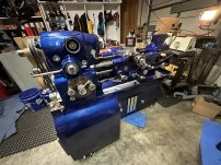
Full tear down and Rebuild of a 10EE Round Dial

image.jpeg
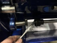
I lubed the feed rod clutch with Super Lube.
image.jpeg
and then slid it together.
image.jpeg
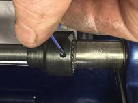
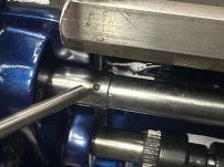
A 6-32 dog point set screw then gets inserted into the clutch.
image.jpeg
I then set the feed rod stop collar for now, but will need to readjust its position once I have a chuck on the lathe.
image.jpeg
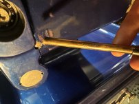
I then slid the lead screw into the gear box collar and drove in its #3 tapper pin to secure it.
image.jpeg
I can now install the Feed Rod Plate. I being by adding Tef-Gel to the bolt threads.
image.jpeg
I slide the Feed Rod plate onto the two shafts, and then very loosely tighten then its mounting bolts.
image.jpeg
I then drive in its large alignment pin.
image.jpeg
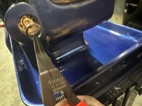
I then place the retaining ring onto the lead screw.
image.jpeg
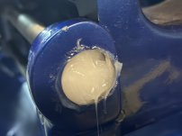
and then pack the cavity full of Super Lube as there is no provision to lubricate this under normal operation. I can then tap in its dust cap.
 
image.jpeg
I then tap in its dust cap and then fully tighten down the brackets two bolts.
image.jpeg
I then use Tef-Gel to prep the spindle for its cam locks.
image.jpeg
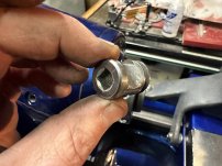
These small shouldered bushings are what hold the cams in place. They have bore on the backside that holds there springs in place.
image.jpeg
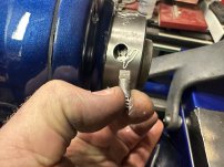
The cams all have a notch that is in alignment with the mark on them.
image.jpeg
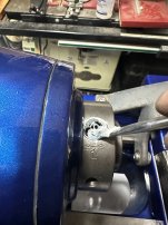
The cams go into each of their bores, then I install the bushings that retain them.
image.jpeg
and finally install the screws that retain the spring loaded bushings.
image.jpeg
image.jpeg
All of the major mechanical portions of the lathe are now done! I still need to paint the drive end covers, and some small parts, plus I need to take the various knobs, plaques, RPM bezel, etc in to get chromed when funds allow. Finally I'll need to finish sorting the power for it. Still more work to be done on the conversion to single phase. It's taken me 3 years (lots of big breaks for work and life events) and a hell of a lot of sweat and countless hours to get to this point. Quite frankly when I started I honestly didnt know if I could complete this project or if it was going to be over my head. I've had a hell of a lot of enjoyment out of working on it to get to this point and learned more than I ever imagined. More to come, but next on my list if a good cleaning of the shop as the lathe parts have taken up every inch of every horizontal space for the last 3 years.
 
Beautiful job. I can't wait to see how it turns. After doing a couple of lathe rehabs- not to your level -, I decided to send my CVA out to have the bed ground and saddle reworked. I hope to get it back after a year next week and anxious to see how the tests compare to my other machines. Chasing tenths costs money but this experiment should give me a clue as to whether it is worth it.

Great write up of the process. Your round dial is very similar to my early CVA.

Dave
 
Ok, its finally time to put the Spindle back in!
View attachment 417602
The threads for the spindle are 60MM with a thread of 18TPI. Nothing like a combo on English and metric to make things interesting, but this is indeed the standard for a N-12 bearing nut.
View attachment 417603
Old nut on the left. New o the right. Even tho its an odd ball metric / English thread combo its a standard off the shelf part at McMaster. My old nut doesn't want to thread on smoothly and neither does the new one. I need to chase the threads. They actually sell a dedicated die for chasing bearing nuts in each size. It's only $370. thats way too rich for my blood for a one of use.
View attachment 417604
So I coated the spindle threads with Dykem.
View attachment 417605
I then picked up a universal thread chaser on Amazon for $40 Lots of options and they clearly are all the same import item, so I ordered the cheapest ones. It was actually better built than I expected and came with a full set of chasing dies for English and metric. So I installed the 18TPI die.
View attachment 417606
I found the easiest way to use it, is align the teeth of the die to the threads in the middle of the threaded section, then run it forward / reverse chasing all of the threads. After each pass give it a ⅛ turn of the handle to tighten it against the threads to take another pass.
View attachment 417607

5 passes latter, all of the dyekem has been removed and I have clean threads!
View attachment 417608
The new bearing nut easily goes on by hand now.
View attachment 417609I then placed both of the bearing spacers and the rear bearing retainer into the ultrasonic, spindle nose side down and let it do its job. We want everything as clean as possible.
View attachment 417610
While those parts were washing, I moved on with modify the bearing nut to lock in place. First I placed into in the mill vise and used a square to align it vertically.
View attachment 417611I used an edge finder to find the center of the flat section. I then spot drilled it.
After the first pass with the thread chaser did you see a particular area that was damaged, or was it just overall off a little?
 
looking like a lathe at last and a very pretty one.

For the lead screw and other shaft bearings, if you want to be able to regrease them you could drill and tap the dust covers for a grease zerk
 
...


View attachment 418217
It's surprising that there is no provision to lube these bearing in service. Adding a Zerk fitting may not have been a bad idea, but problem with that is no wear for the new grease to push the old out to. ...
I added grease fittings to mine. The feed-rod plug is a thick piece of steel, so I just drilled/tapped it for the fitting. The leadscrew plug was stamped steel, so I made a new plug out of brass:IMG_2516.jpg

The excess grease can escape around the leadscrew or feed rod:
IMG_2517.jpg

My leadscrew also had a lot of wear, so I replaced it with a new, old stock leadscrew from Monarch. (They told me it was the last round-dial leadscrew that they had.) Picking up the taper pin hole in the end of the leadscrew (drilled off center and at an angle) took some careful machining. I posted about it here:
 
Wow, what a fantastic write up and beautiful job on the lathe!
Thank you. It's been a fun process and the forum here has been a wealth of knowledge. Hopefully documenting it all to this level will help the next guy.
Beautiful job. I can't wait to see how it turns. After doing a couple of lathe rehabs- not to your level -, I decided to send my CVA out to have the bed ground and saddle reworked. I hope to get it back after a year next week and anxious to see how the tests compare to my other machines. Chasing tenths costs money but this experiment should give me a clue as to whether it is worth it.

Great write up of the process. Your round dial is very similar to my early CVA.
Thanks!
looking like a lathe at last and a very pretty one.

For the lead screw and other shaft bearings, if you want to be able to regrease them you could drill and tap the dust covers for a grease zerk
I think this is a good idea.
I added grease fittings to mine. The feed-rod plug is a thick piece of steel, so I just drilled/tapped it for the fitting. The leadscrew plug was stamped steel, so I made a new plug out of brass:View attachment 418321

The excess grease can escape around the leadscrew or feed rod:
View attachment 418322

My leadscrew also had a lot of wear, so I replaced it with a new, old stock leadscrew from Monarch. (They told me it was the last round-dial leadscrew that they had.) Picking up the taper pin hole in the end of the leadscrew (drilled off center and at an angle) took some careful machining. I posted about it here:
Thanks Cal, I was wondering if it would have space to squeeze out. I think I'll add them next time I have it apart. I'd love to find a new lead screw at some point, but I think mine is more than serviceable for the time being. I'm also going to be looking out for new Forward / Reverse clutch gear / bearings as those are the 3 parts on my machine that have significant wear. That being said, I gotta wait for the bank account to recover post divorce before I have funds for what will probably be expensive parts!

Has anyone had much luck with those DIY copper / nickle/ chrome platting kits? Given the quote I got locally for doing all of the small knobs/ etc. I think it may be my only viable option. I feel like they gave me a go away price not wanting to do it as they are booked out months.
 
Has anyone had much luck with those DIY copper / nickle/ chrome platting kits? Given the quote I got locally for doing all of the small knobs/ etc. I think it may be my only viable option. I feel like they gave me a go away price not wanting to do it as they are booked out months.
I've done nickel and silver playing on a very small scale with the smallest Caswell kit. It's the one where they give you a little wand to brush the playing solution on the electrified part, but usually I just submerge both. It can be fussy, but usually works OK in the end. I am matching other worn parts on antique instruments, so "not perfect" is OK for my needs.

Be sure to vet any playing shop you might send those parts to... not all of them are used to (or care about) working with fragile or non-replaceable parts.
 
Grant your a hell of a hand no matter what your ex wife says about you. :)
A GREAT step by step write up with professional pictures to boot.
You should make a book out of it. How to fix you 10 EE right.
Thanks for taking the extra time to write about and photography every step.

Now that you have practiced on your do you want to do mine. :)
Hal
Haha Thanks! I think I need a break before I take on another major project of this scale. Need time to enjoy the results of this one first! Plus, with my current lady friend, I have less time in the shop than Ive had in the past, and so far thats a good thing.

That being said, at some point, I'd love to find the right I/M 10EE for the right price and do something similar, and or a Moore Jig Bore..... any of those options will definitely be on the back burner until I can move into a place with a much larger dedicated shop space at some point.

I've had a ton of people reach out to me about doing a 10EE book. At the beginning of this project that never crossed my mind. A few people over on Garage Journal suggested I look into Amazon custom publishing, and I think it's actually feasible to do it and have it be a reasonable cost. A book certainly wouldn't be a significant revenue maker, so being able to have it printed cheaply on demand is the key. I just need time to go back and edit the content in a more linear form and fix some grammar / spelling typos that are the results of trying to type with greasy tired hands! I also need to go back and edit the links at the beginning of this thread to direct link to the major sections. I'm all for helping out with resources to make it easier for the next guy, and if a low-cost book helps in addition to the forum posts, then its probably worth doing on my end.

That being said, there is a multitude of different ways to get a similar result, so I hope this thread is an example of what worked for me, and may not necessarily be the best or most efficient way. I think it is on the other hand probably the most detailed thread on it.
 
...

Has anyone had much luck with those DIY copper / nickle/ chrome platting kits? Given the quote I got locally for doing all of the small knobs/ etc. I think it may be my only viable option. I feel like they gave me a go away price not wanting to do it as they are booked out months.
I used a Caswell kit to brush plate the backgear plate. I first used copper, then basically nickle.

Here's a before shot, after polishing it with fine steel wool:
IMG_5120.jpg

And after nickel brush plating:
IMG_5128.jpg

And here's what it looked like after being chrome plated by a local shop:
IMG_5734.jpg

The brush plating was really thin. You would probably have better luck if you submerged it, but I think you need a bigger power supply that the one that comes with the brush plating kit.

I also used the kit to plate the little brass push-rivets that held the plate on, but I guess I didn't take any photos of that; IIRC, I submerged them and they came out pretty well:
IMG_6723.jpg
 
I used a Caswell kit to brush plate the backgear plate. I first used copper, then basically nickle.

Here's a before shot, after polishing it with fine steel wool:
View attachment 418571

And after nickel brush plating:
View attachment 418570

And here's what it looked like after being chrome plated by a local shop:
View attachment 418572

The brush plating was really thin. You would probably have better luck if you submerged it, but I think you need a bigger power supply that the one that comes with the brush plating kit.

I also used the kit to plate the little brass push-rivets that held the plate on, but I guess I didn't take any photos of that; IIRC, I submerged them and they came out pretty well:
View attachment 418573
Cal that looks good. Did you plate with copper first prior to doing the Nickel? If I do og this route, I'll order a DC Lab power supply they are surprisingly cheap, and get a hot plate with a stirring function. Been doing some research in to It, but lots pop stuff to learn before I commit.
 
Yes, the Caswell kit came with both a copper and nickle solution. Although, they called the nickel solution "Copy Chrome". IIRC, actual chrome plating solution is very toxic.

You might want to call the chrome plating shop that did mine:
Ideal Custom Plating​
937 S 6th Ave​
Tucson, AZ 85701​
(520) 882-9090​

The entire plating job, 4 pieces in total, cost $65 in 2010.

Another option might be to have new plates made. Here's brand new round-dial plate that was done by a shop here in Tucson:
EE23233 dialplate5 new round-dial plate - crop.jpg
Last I heard this guy did lots of plates like this for a local machine rebuilder. He took a scan of the plate and created all new artwork in something like Adobe. Can you spot the difference from the original plate?

On edit: correct Caswell plating kit info; add chrome plating cost
 
Last edited:
The new plate was done by Ted Miller of Tucson Trade Engraving. IIRC, he used a chemical etching process; definitely not laser. Unfortunately, Ted doesn't seem to be in business any more. Steve Marquess paid $144.58 for the plate, including shipping and a $50 design charge. Here's the thread that talks about it, as well as the chrome plating for my dial:
 
Last edited:


Back
Top