What's new
What's new

g71 issue - tool unexpectantly returning to X0/Z0

bengineer08

Plastic
Joined
Jun 17, 2022
Location
Northern KY / Cincinnati area
Hello all,
I've got a G71 external rouging issue I can't figure out. Running on a Miyano lathe, Fanuc 0T. Everything seems to run great, until it gets to the end of the roughing cycle, then it immediately makes a bee line for X0 Z0. I anticipate it should be going to X 30 Z5, but no. It's likely I'm programming it wrong (I'm teaching myself), but this looks very similar to the examples I've dug up. I keep looking over and over the gcode and I don't see where it thinks its supposed to be going there. If anyone could take a look, I'd greatly appreciate it. I think it happens on the G70 as well. Z zero is the front of the part.

05555
G21 G80 G40;
T0101;
G50 S2500;
G96 S525 M03;
G00 X30.0 Z5.0;
G01 Z0.01 F01;
X-0.5 F0.05; (FACING)
G00 X30.0 Z5.0;
G71 U1.0 R1.0;
G71 P100 Q200 U0.2 W0.05 F0.1;
N100 G00 X14.8;
G01 G42 Z0 F0.2;
X15.8 Z-0.5;
Z-17.0;
X20.0 Z-20.64;
Z-25.0;
X25.0;
Z-38.0;
X30.0;
N200 G40 X30 Z5.0 F20.0;
G70 P100 Q200;
G28 U0 W0;
M05;
G97;
M30;
 
N200 G40 X30 Z5.0 F20.0;
I suspect your problem is in the Q line of the profile. There’s no need for this line at all, since the cycle will automatically return to the starting point in rapid mode (G0).

G50 S2500;
G96 S525 M03;
With this cutting speed, the RPM will be clamped throughout the whole cycle.
In order for you to take advantage of CSS at 525m/min at a profile with a minimum diameter of 15.8mm, you would need a spindle capable of at least 10k RPM.
G71 U1.0 R1.0;
G71 P100 Q200 U0.2 W0.05 F0.1;
N100 G00 X14.8;
G01 G42 Z0 F0.2;
Here you are roughing with a feed of 0.1mm/rev and finishing with a feed of 0.2mm/rev. It should be the other way around. Rough out the material with a heavier feed and finish with a lighter feed to get a better surface finish.

I would also remove the G42 and G40 from the G71 cycle, and only apply tool nose compensation one line before the G70 cycle is called and cancel one line after.
 
Hello all,
I've got a G71 external rouging issue I can't figure out. Running on a Miyano lathe, Fanuc 0T. Everything seems to run great, until it gets to the end of the roughing cycle, then it immediately makes a bee line for X0 Z0. I anticipate it should be going to X 30 Z5, but no. It's likely I'm programming it wrong (I'm teaching myself), but this looks very similar to the examples I've dug up. I keep looking over and over the gcode and I don't see where it thinks its supposed to be going there. If anyone could take a look, I'd greatly appreciate it. I think it happens on the G70 as well. Z zero is the front of the part.

05555
G21 G80 G40;
T0101;
G50 S2500;
G96 S525 M03;
G00 X30.0 Z5.0;
G01 Z0.01 F01;
X-0.5 F0.05; (FACING)
G00 X30.0 Z5.0;
G71 U1.0 R1.0;
G71 P100 Q200 U0.2 W0.05 F0.1;
N100 G00 X14.8;
G01 G42 Z0 F0.2;
X15.8 Z-0.5;
Z-17.0;
X20.0 Z-20.64;
Z-25.0;
X25.0;
Z-38.0;
X30.0;
N200 G40 X30 Z5.0 F20.0;
G70 P100 Q200;
G28 U0 W0;
M05;
G97;
M30;
Depending on the vintage of the Fanuc 0T, most later versions no longer allow G41/G42 within the cycle.
Also the Q line is extemporaneous, I would get rid of the "X30." line above it, and also get rid of the "Z5.0" on the Q line.
 
X30.0;
N200 G40 X30 Z5.0 F20.0;
As mentioned by Douglas, TNR Comp will be ignored in the G71 Cycle. In your example program, because the Profile is monotonous in the X+ direction, extra material will be left on Tapered and Radius features, in addition to the Finish Allowance specified. As the same profile data is being used by the G70 Cycle and as TNR Comp is executed by G70, the G42/G40 have to remain in the Profile Description between the "P" and "Q" referenced Blocks. However, the N200 G40 X30 Z5.0 F20.0 is superfluous and the Z5.0 is creating a Non-monotonous profile in the "Z" axis, which will cause issues. Change the above code in your program to the following:

N200 G40 X30.0

When a Profile Description contains a Concave Feature, this is referred to a Non-monotonous X profile and as TNR Comp is ignored in the G71 Cycle, such a profile will result in a profound overcutting by Trailing Edge of the cutting tool insert. Therefore, when roughing a Profile that includes a Concave feature with a G71 Multi Repetitive Cycle, it is better to include THR Compensation in the Coordinates of the Profile Description and not use G41/G42 to compensate for the TNR by the Control.

Regards,

Bill
 
as TNR Comp is executed by G70, the G42/G40 have to remain in the Profile Description between the "P" and "Q" referenced Blocks
Not necessarily.
G42 and G40 can also be placed just before and after the G70 block.
I consider it a better structure, as it makes it obvious what is happening (G70, not G71, using TNR).
 
Not necessarily.
G42 and G40 can also be placed just before and after the G70 block.
I consider it a better structure, as it makes it obvious what is happening (G70, not G71, using TNR).
I don't normally used TNR Comp by the Control on a lathe, one reason being that if using G71 when there is a Concave Feature in the profile, its becomes an issue with possible overcutting of features in the profile with the Trailing Edge of the tool. It's simply simpler to include the TNR Comp in the profile coordinates and not be concerned if the part is going to scrap after the Roughing Cycle.

Its not necessary, but I find it tidier to have the roughing cycle as a complete package if G70 is going to be used to finish the profile. Its generally better to Start and Cancel TNR Comp with a move command; easily accomplished with the OP's example corrected as follows:

G71 P100 Q200 U0.2 W0.05 F0.1;
N100 G42 G00 X14.8;
G01 Z0 F0.2;
X15.8 Z-0.5;
Z-17.0;
X20.0 Z-20.64;
Z-25.0;
X25.0;
Z-38.0;
N200 G40 X30.0;
G70 P100 Q200;
 
When I was new to programming, whenever I saw G41/G42 withing P and Q blocks, I used to believe that the roughing cycles are using it. That is why, I prefer to keep these with G70.
It is a matter of style.

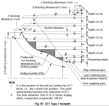
By the way, do you have an example of a monotonic profile where type 1 is better than type 2? I am of the opinion that if both are available, there is no good reason to use type 1. Type 2 would actually reduce the cycle time, as it has no step-removal pass in the end, the way a type 1 cycle has. Your opinion?
To be honest I always use type 2. It leaves a better finish and the retract on type 1 is kind of wonky at times. Then again I always long code my finish passes and don't use g70 lol. I guess we all got our own little ways about us. I can not think of a single time type 1 is better. Maybe Bill has a good example. I would be interested to know.


Back
Top