What's new
What's new

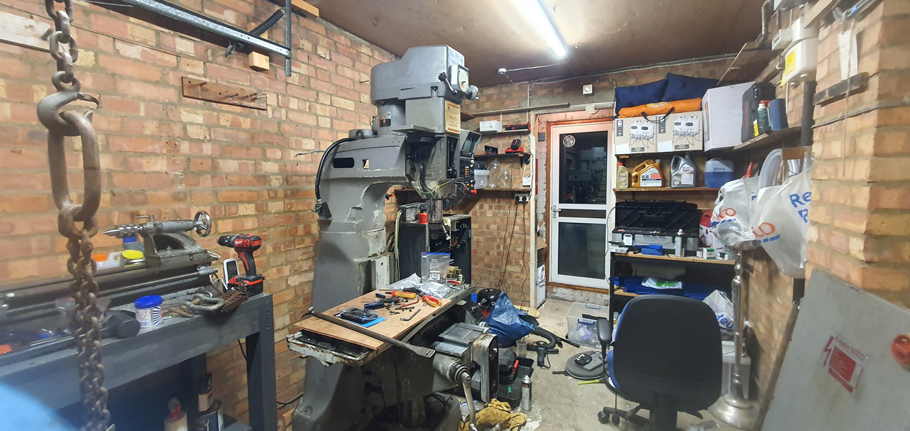
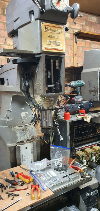
Got Free Interact 1 Mk1

I guess what I am saying is the high voltage is good, which is the hard part, so don't throw it away
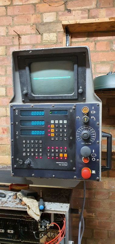
Heidenhain monitors are heidenhain specific.
They are similar to MGA monitors from old, old, old PCs but the logic is inverted. I have an old monitor sitting here that I can use in an emergency, when you wire it into the control video out it shows inverted, bright background, visible retrace, but you can see what is going on anyway
I saw a clever guy on youtube who managed to hook up a VGA monitor to his as well, not a perfect result but you could see what was going on, i was thinking i might try this just to get me out of trouble. Hopefully i can get this spare VDU from the guy quite quick.

I have searched online about trying to replace the deflection amp but so far not come up with much specific info, seems like its probably a repair shop job.

Thanks

Alex
 
Hi Guys,

So bit of an update on the Interact. Got the new VDU from the friendly and helpful guy. Plugged it in, got the parameters entered ok. Reset the machine, attempted to get it to move - nothing!
I started trying to trace the problem and quickly remembered that the wires for Fast Travel in the XY Joystick were broken, without checking the drawing i repaired them to see if that helped correct the problem.

Powered up the machine again, pushed the Power Enable and poof the machine shut off and quickly i realised CFU1 had blown. I triple checked everything and especially the XY Fast Travel wiring as i noticed this was 110v. Upon reboot it seemed to be ok, i tried Power Enable again and the machine tripped / rebooted then had a message stating TNC-Electronics Defective, jibberish on the DRO Displays. I triple checked all the wiring from when we moved the machine, everything is correct as it was taken apart. Not sure what could have caused this? I intially thought maybe i'd sent 110v from the Fast Travel button into the 24v DC of the joystick but all the wiring is intact etc. I have not had a chance to seriously sit down and troubleshoot yet, but im worried the control is now dead. I can hear CR10 buzzing and spazzing out a bit, this worries me as its driven directly from the MDI, i powered down and checked all the relays and cycled the contactors a few times manually. When powering up it will usually return to normal but sometimes return to electronics defective.

Anyone got ideas of common things to check? My engineer friend has given me a couple of items to check on the input side. I also attach a scan of the wiring Diagram, apologies it looks like a pirates treasure map but its the highest resolution one i have which i scanned in myself.


Thanks

Alex
 
If it operated to a point before you 'fixed' the wiring, I think I would unfix it
you either skipped a bunch of steps in your explanation, or you did not pass over the ref marks
 
If it operated to a point before you 'fixed' the wiring, I think I would unfix it
you either skipped a bunch of steps in your explanation, or you did not pass over the ref marks
Genuinely this is the reason im at a loss, before re-joining the XY Fast Travel Button wires, i had the Amps powered up (or at least Green LED's visible on them), but no movement, even in the override mode. Once i had fixed the wiring (literally rejoined two broken wires in the joystick, dont think there is polarity there?) The whole machine now trips when Power Enable is pressed.

If i had made a mistake or thought i had, then i would openly give this information to help troubleshoot.

I will remove the wires again tonight and try again.

Thanks

Alex
 
did you pass over the reference marks when you first fired it up? The machine will not move until you do that
I do not know what you might have done with those wires
 
did you pass over the reference marks when you first fired it up? The machine will not move until you do that
I do not know what you might have done with those wires

Well a few bits of progress last night. I am still dumbfounded by the fast travel push button, i stripped the whole joystick again, visually checked all the wires, the top contact of the actual push button. Check for grounding issues with the meter to the metal body of the joystick. All checks out as should - but when its wired in it sends the controller on the fritz. I fitted an entirely new push button instead and it works perfectly!

I also had the homing procedure wrong, i was not aware that you had to push the cycle start button fort each one. I did this and i got all axis homed correctly! Now i can move onto tidying up the machine and getting my VFD installed.

Whilst playing with the machine and jogging the Axis, it eventually gave me a Gross Positioning Error, im led to believe this is because it isn't holding the expected position / not keeping up - could this be a lubrication problem? Any way to force the pump to prime a shot?

Thanks

Alex
 
.....Whilst playing with the machine and jogging the Axis, it eventually gave me a Gross Positioning Error, im led to believe this is because it isn't holding the expected position / not keeping up - could this be a lubrication problem? Any way to force the pump to prime a shot?

Thanks

Alex
Gross positioning error, yes, it sometimes happens. To me when it was taking too much of a cut. E-stop, rehome, good to go. I suppose it could be that the servos need to be tweaked?

The lube pump can be operated manually, if it's a Bijur with a plunger on top. Pull the plunger up and release it. The related pressure gauge should go up (75psi, IIRC), then slowly return to 0.
 
GPE means you need to adjust your servos
When I'm fast travelling or using the joystick to move at feed rate (with the spindle on) the machine is perfect.

The Rotary Wheel is now totally dead I think?

It started only working in one direction and giving GPE in the other. Now it gives GPE as soon as you select it from the controller.

On the plus side I have been provided with a copy of mastercam and Heidenhain post which I'm about to get setup.

Thanks

Aex
 
hit the big red button
means the machine cannot move thus should not GPE
change the interpolation factor on the screen, think it goes from 1-5 or something, IIRC higher number is slower
slowing down the handwheel should stop the GPE
if it does not there are more wiring errors than the joystick
 
I have forgotten to take a picture of it, but the perspex cover which covers the Dial has what looks like an oiler mounted in it. A ballbearing fitted to it directly inline with a whole under it. Ill take a picture later when i get in.

Ok so progress, i have mostly re-assembled the machine, nearly gave myself a hernia lifting the spindle / Pulley housing on, as well as the Z Axis Assembly. Engine Hoist couldnt get in there nor would go high enough to make it work so i had no choice but to lift by hand. Wasn't as bad as i imagined intially.

20221007-211319.jpg


20221007-211328.jpg


20221009-182200.jpg


Z Axis Joystick was damaged, a wire had been pulled from the microswitch on the back, this probably happened during either of the moves. Luckily i had a bag of spare ones from my 3D Printers laying around so quickly replaced it.

20221007-221118.jpg


20221007-221525.jpg


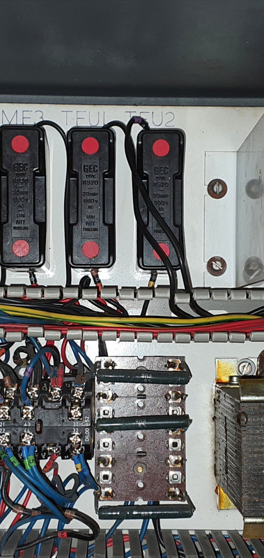
I know for many people here this will be a simple task but i needed assistance with wiring the control to 230v Single Phase, my engineer friend came to my rescue. The primary on the transformer should be moved over to to the correct terminal.

Screenshot-20221009-171308.jpg


After this you can disconnect and cap the wires that go into the bottom of the TFU1 & TFU2 Fuses, after you have done this take your Neutral from your plug to the bottom of TFU1 and the Live to the bottom of TFU2.

Screenshot-20221009-171520-Gallery.jpg


The controller powered up but at first it was erratic, DRO readouts were flickering and changing numbers. I powered down the machine, checked all the connections (I had forgotten to connect the Z Axis Servo & Encoder Wires during re-assembly). I also put 3 new batteries in the TNC145, and moved the earth from the 3 Pin Plug from ESS on the transformer to a Earth on the cabinet. One or all of these things corrected the erratic behaviour.

Unfortunately the VDU is broken, i have read online one of the amps in it has probably failed or something, luckily i met a nice guy on the facebook group who is going to donate me his old one that he took out when he retrofitted his.

20221009-124208.jpg


20221009-182219.jpg


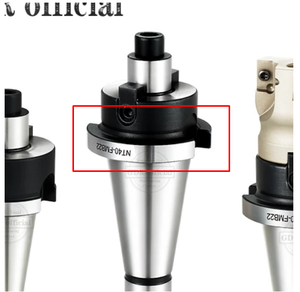
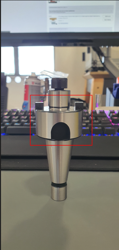
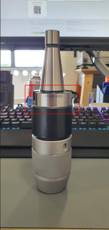
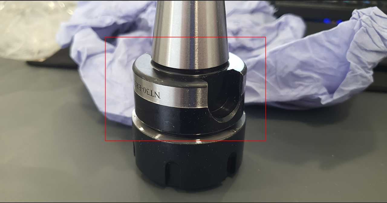
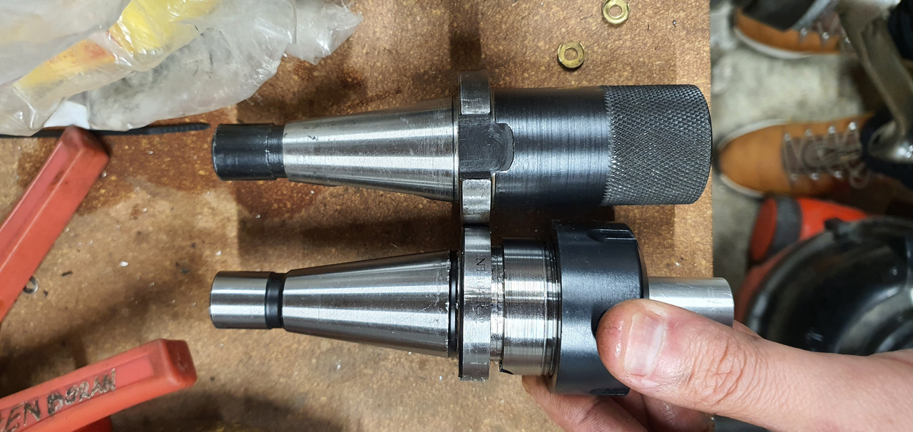
On a separate note, i ordered some NT30 ER32 Tool Holders from China, according to the drawing they should have been compatible for the QC30, however they arrived incorrect. They refunded me the cost and let me keep the tool holders, having recently bought my first lathe i set out to try and modify them to work.

The flange was much too thick, on my existing Erickson too holder that came with the machine, the flange was ~8.2 - 8.8mm (IIRC this was a few weeks ago now), i used a grooving / parting tool to rework the flange, by putting a 4mm Groove in at that position, and also reduce the tool holder body down to 35mm to match the Erickson one. I then reduced the rest of the flange slightly so that it would happily fit inside the nut (non - essential).

HOWEVER, my tool holder refuses to go far enough into the nut for the retaining (dogs, clips, correct name???) to slide over the flange, i even reduced the flange a further ~0.5mm bit by bit but it still wont grab it.

Measuring and comparing the rest of the tool holders they seem pretty much identical, i must be missing something obvious here? Possibly the taper is incorrect and binding part way into the bore? Suggestions welcome, i will probably have to buy the expensive ones from Poland @ £90 a holder.

Screenshot-4.png


Screenshot-5.png


Screenshot-2.png


Screenshot-1.png


Screenshot-13.png


Dont judge my machinist skills on the lathe, this is the first thing i ever did with it!!

20221010-212132.jpg


Thanks

Alex
It’s likely that the gage line is in the wrong place not just that the flange is too thick. You need a fixture to measure it, or use the spindle itself. Basically you need to support the tool holder by the taper and then use an indicator to measure the location of the flange, then swap to your new tool holder and see if the flange is in the same location.

I made some tubing that was faced on the ends and bored to match KS200. I use it when making tool holders to get the bayonets located correctly as well as the base for presetting tool length offsets using a surface plate and height gage.
 
hit the big red button
means the machine cannot move thus should not GPE
change the interpolation factor on the screen, think it goes from 1-5 or something, IIRC higher number is slower
slowing down the handwheel should stop the GPE
if it does not there are more wiring errors than the joystick
Ok so, I've a bit of news. I was approached by a local engineering shop on Facebook who were scrapping an Interact 2 and offered me the chance to go strip it for parts before it went - which I did.

I got all of the electronics, joysticks, LCD Screen for it etc. And a whole box of other spare parts including joysticks etc. Very happy with that!

So back to the encoder wheel, I rung through all the wires back to the milspec plug on the back of the TNC. All of the wires had no breaks etc. So I though maybe the encoder was faulty.

I swapped the encoder for the new and known working one I got off the Interact 2.

So previously the wheel would work in - and stutter in + then GPE.

The new wheel also works in - but does nothing at all in +, and no GPE at all. So obviously the signal is not making it to the TNC I imagine.

Checked the wires again, all rung through on the meter fine. Resistance between the pairs was different though, can't remember by how much though, and I don't have an OS to check it properly.

I even tried the encoder board from the spare 145 I took from the interact 2, which wouldn't even home the machine properly.

So at this point I'm going to forget about the wheel and maybe even gettin the TNC to work at all and just make haste with the retrofit. Will be hard to touch off tools etc without the wheel and I'm not sure what else could be wrong with it.

Alex
 
You are best off making sure that the machine operates as it is and deciding to retrofit afterwards. The existing control, while memory limited is very reliable. If you do not have the patience to troubleshoot a control that runs 90 percent, I fear for the prospects of retrofitting a machine
 
You are best off making sure that the machine operates as it is and deciding to retrofit afterwards. The existing control, while memory limited is very reliable. If you do not have the patience to troubleshoot a control that runs 90 percent, I fear for the prospects of retrofitting a machine
The Joystick movements work fine. I can engage the spindle and do feed rate movements with the joystick, and i can also do fast travel movements with the Joystick and Button.

With the new wheel it doesn't give a GPE at all now, Its just the wheel is only working in one direction (- Only).

The wiring rings through on the meter to the plug on the TNC and visually i inspected it and there is no tired areas, the outer sheath and shielding is good throughout the cable so i assume there is not an intermittent / stress related problem with it either. I saw mentioned on a forum (which i now cannot find) that there is way to change the display to show programmed position instead of actual position?

In regards to the retrofit yes i agree its not a simple task but all of the motors and encoders would be going anyway, and the handwheel would be replaced with a universal MPG Pendant Type. I understand i probably look to have short patience but im just weighing up the trade off getting the wheel to work "just because" whereas i could just probably use the joystick and very slow feed rate to touch off using an edge finder.

Another task im currently involved in is checking the operation of the Lubrication System. The fitting at the bottom of the casting, the one way valve there (i think its a one way valve?) Was totally blocked, i need to get a replacement for this, and i've also been trying to clean the other easily accessible ones. I gather there is no way to accurately check their function (especially the ones under the table) without stripping the machine and checking for the presence of oil? I saw a video by H&W Machine Repair and Rebuilding where he said you can replace them all with the same type?

Thanks

Alex
 
from the 151 service manual:
handwheel pinout
1 0 deg + gn
2 0 deg - ge
3 UL+ br
4 UL - ws
5 90deg+ bl
6 90 deg - rt
9 0 volts gn

colors should help identify on the board end


Back
Top