Friggin' excellent! (That's American for yes!)
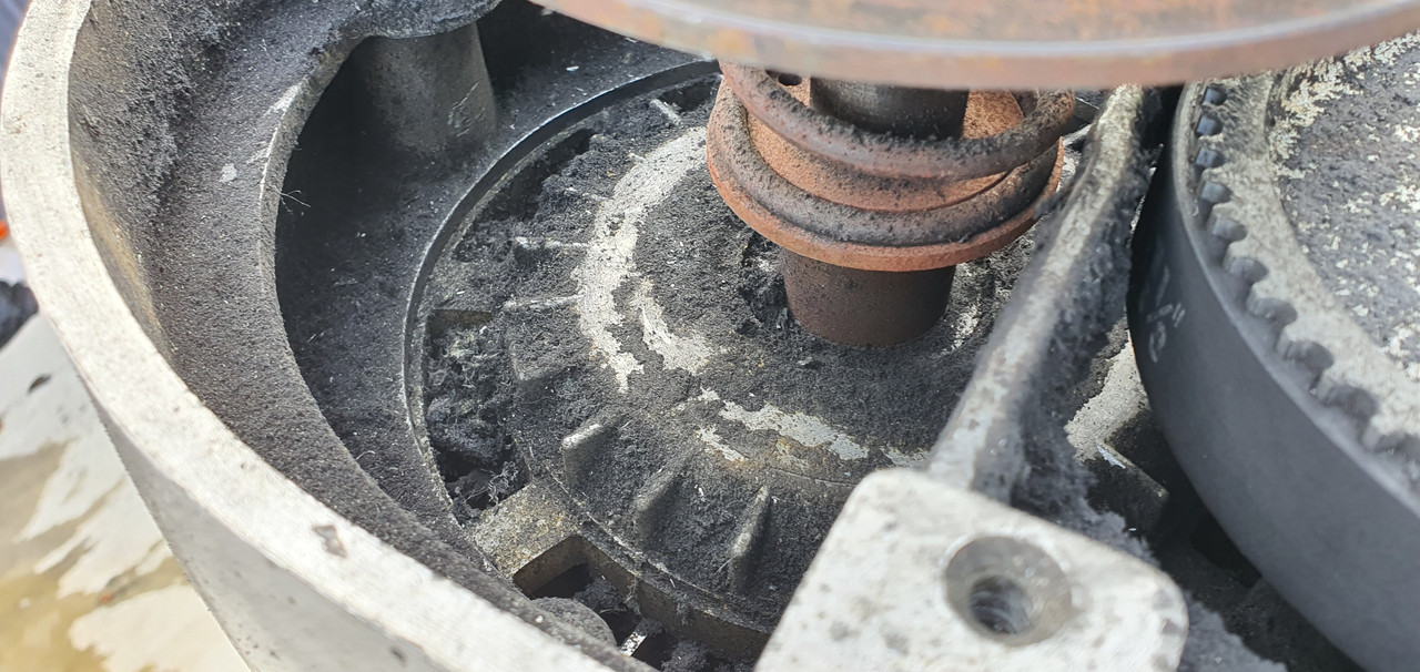
What you're thinking may be an oiler may be the remains of the knurled hand screw that locks the dials to the handle extension. Get that sorted and the dials will turn with the handle.
I have forgotten to take a picture of it, but the perspex cover which covers the Dial has what looks like an oiler mounted in it. A ballbearing fitted to it directly inline with a whole under it. Ill take a picture later when i get in.
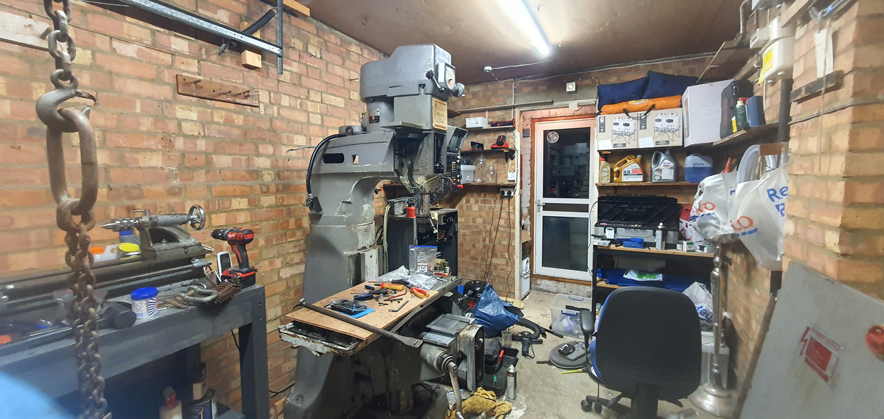
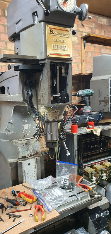
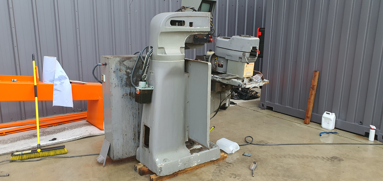
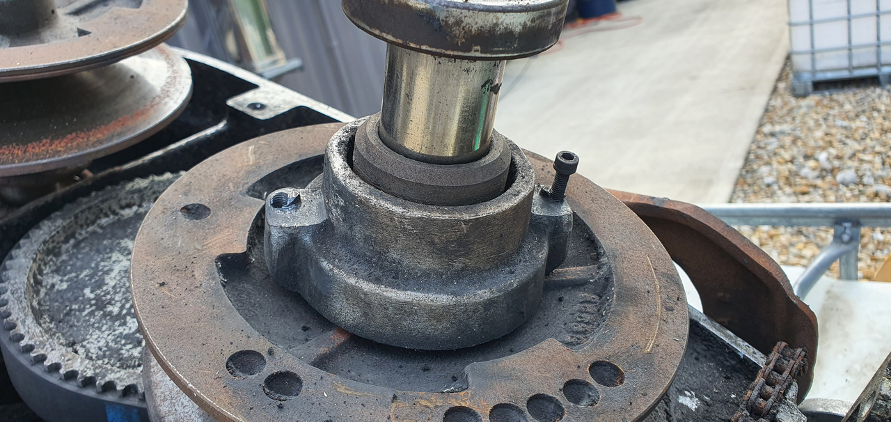
Ok so progress, i have mostly re-assembled the machine, nearly gave myself a hernia lifting the spindle / Pulley housing on, as well as the Z Axis Assembly. Engine Hoist couldnt get in there nor would go high enough to make it work so i had no choice but to lift by hand. Wasn't as bad as i imagined intially.
Z Axis Joystick was damaged, a wire had been pulled from the microswitch on the back, this probably happened during either of the moves. Luckily i had a bag of spare ones from my 3D Printers laying around so quickly replaced it.
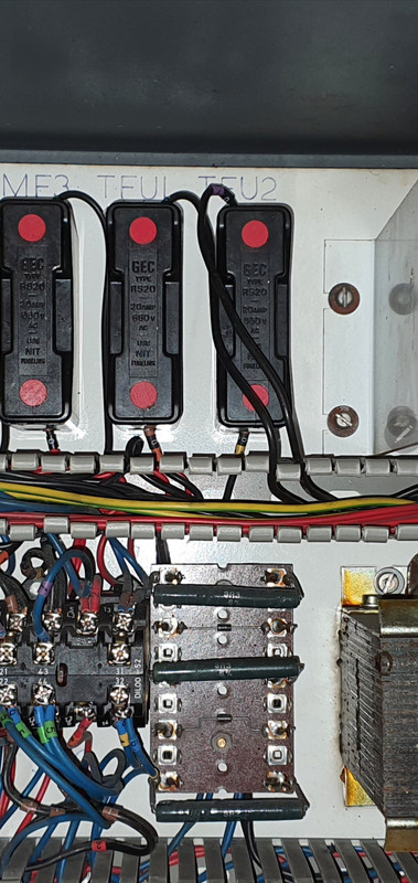
I know for many people here this will be a simple task but i needed assistance with wiring the control to 230v Single Phase, my engineer friend came to my rescue. The primary on the transformer should be moved over to to the correct terminal.
After this you can disconnect and cap the wires that go into the bottom of the TFU1 & TFU2 Fuses, after you have done this take your Neutral from your plug to the bottom of TFU1 and the Live to the bottom of TFU2.
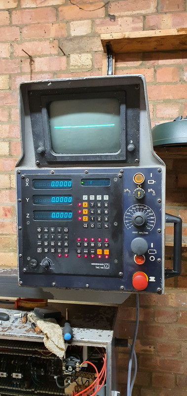
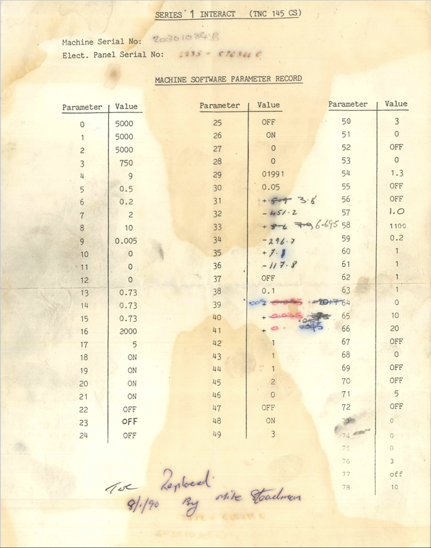
The controller powered up but at first it was erratic, DRO readouts were flickering and changing numbers. I powered down the machine, checked all the connections (I had forgotten to connect the Z Axis Servo & Encoder Wires during re-assembly). I also put 3 new batteries in the TNC145, and moved the earth from the 3 Pin Plug from ESS on the transformer to a Earth on the cabinet. One or all of these things corrected the erratic behaviour.
Unfortunately the VDU is broken, i have read online one of the amps in it has probably failed or something, luckily i met a nice guy on the facebook group who is going to donate me his old one that he took out when he retrofitted his.
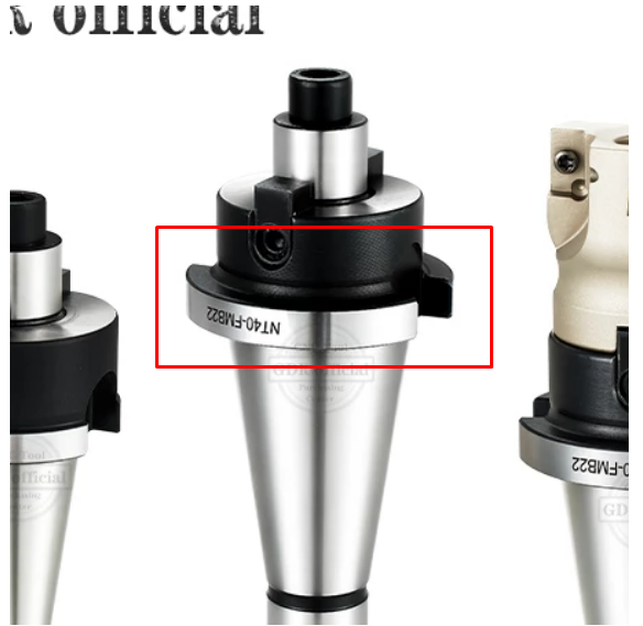
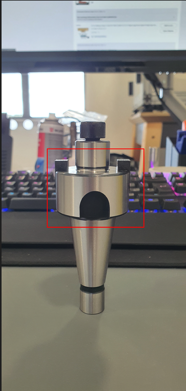
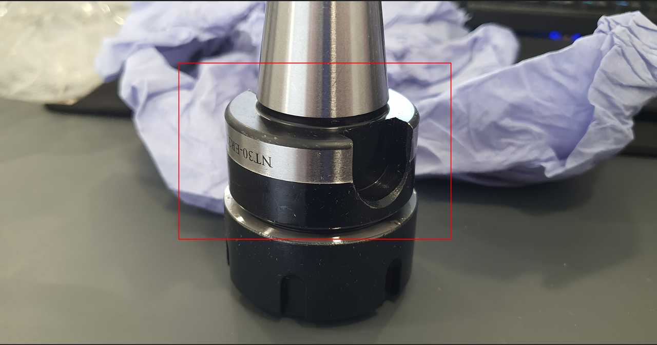
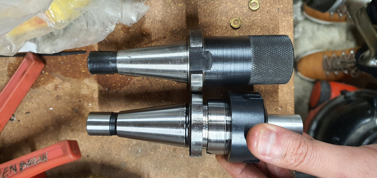
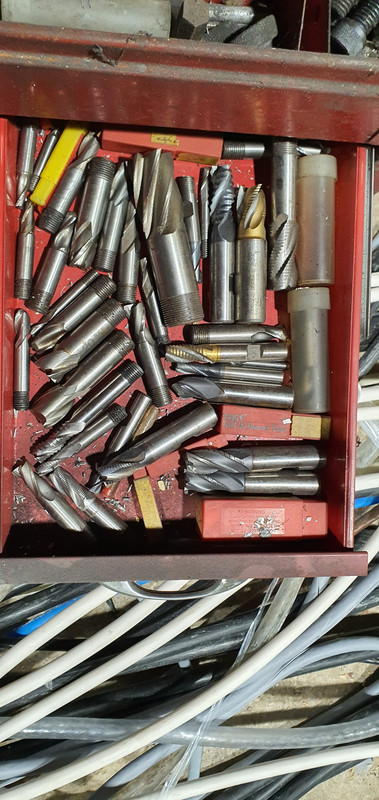
On a separate note, i ordered some NT30 ER32 Tool Holders from China, according to the drawing they should have been compatible for the QC30, however they arrived incorrect. They refunded me the cost and let me keep the tool holders, having recently bought my first lathe i set out to try and modify them to work.
The flange was much too thick, on my existing Erickson too holder that came with the machine, the flange was ~8.2 - 8.8mm (IIRC this was a few weeks ago now), i used a grooving / parting tool to rework the flange, by putting a 4mm Groove in at that position, and also reduce the tool holder body down to 35mm to match the Erickson one. I then reduced the rest of the flange slightly so that it would happily fit inside the nut (non - essential).
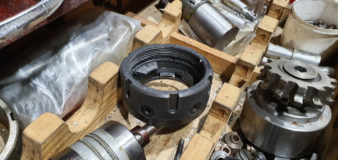
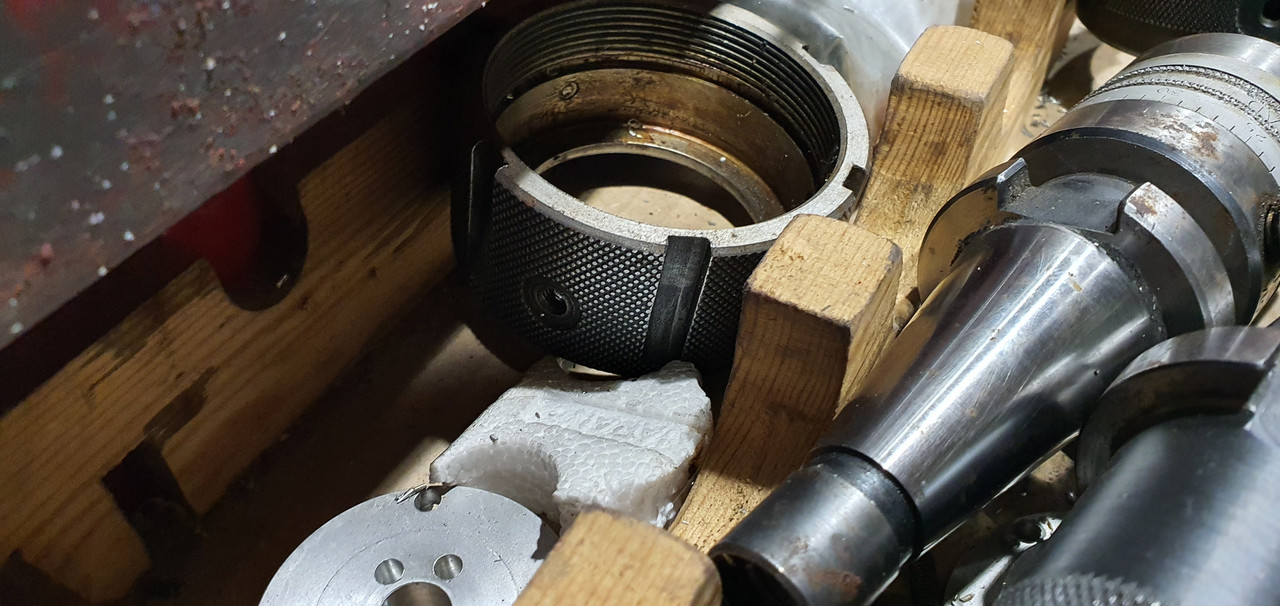
HOWEVER, my tool holder refuses to go far enough into the nut for the retaining (dogs, clips, correct name???) to slide over the flange, i even reduced the flange a further ~0.5mm bit by bit but it still wont grab it.
Measuring and comparing the rest of the tool holders they seem pretty much identical, i must be missing something obvious here? Possibly the taper is incorrect and binding part way into the bore? Suggestions welcome, i will probably have to buy the expensive ones from Poland @ £90 a holder.
Dont judge my machinist skills on the lathe, this is the first thing i ever did with it!!
Thanks
Alex


")