What's new
What's new

Help troubleshooting a starting issue with large motor via RPC

On the plate:
Max Accum H.P. 20

Your number is 22.5. Right over the boundary of 20.
If you could get the Wadkin motor spinning and then applying Wadkin power, you might get clear.
But that is not realistic. Boundary conditions exist and you are not the first.
 
Based on past conversations with Kay tech support, I don’t think that max accum 20 hp figure includes the 10 hp idler of the RPC itself.

It is my understanding that it can start a single 10 hp motor (or ~ equivalent amps) as the largest single load but, if enough supply is present and wire gauge is appropriate, then up to 20 hp can be run simultaneously, if started separately.

Yes, a 12 hp / 27.4 amp single motor is obviously on the edge of that largest single motor capacity. I have spoken with Kay tech support about this specifically a few days ago and they say the HP ratings they put are pretty conservative and that they think it should start the shaper load given RPC and supply details, and it sounds like the machine contactor O/L is undersized.
 
I did not recognize the box being on the BACK of the Wadkin. Thought it was part of the RPC.
See post #4 from SAF. That is correct.

The quick dirty test is to disconnect the OL function and see what happens.
It will probably work but why not buy the correct part first. Those parts can sometimes
be swapped in as from a different brand. As long as the spacing on the connections are the same distance apart.

This I see here a lot. Changing a working voltage from 230 to 460 or 460 to 230.
The control voltage coils or OL has to change as well. Sometimes people don't know this.

Now you can go on your vacation. And if you are taking a cell phone you can shop around
for the new part. No more thinking about what to do, just how much to spend. If it was me
I would see about a direct replacement. Notice in the 4th pic how worn the yellow OL wheel is worn
in the screw driver slot. That indicates something.
 
Last edited:
According to the drawing title block the motor is a dual voltage wye start, delta run,12 lead model, some were equipped with thermal sensors embedded in the windings, and it notes that if it is so equipped, they should be connected into the motor starter protection circuit. Checking the manual avalible online, it appears that the standard models came with motors of 5, 7.5, and 10 HP motors, different spindle speeds were obtained with multi stepped pulley sets and the motor was a single speed 3480 RPM @ 60Hz. Wye delta motors and starters are normally used on heavier starting and high speed loads to reduce the startup current draw on the supply system, this tells me that the designer considered it a heavy hard starting load, checking the manual and parts list it appears that they used a single 3Φ starter, and not a wye delta model that would consist of three contactors to reduce the starting current. Your motor is larger than the standard models, 12HP and Tri voltage rated, so it is not the norm for this machine, goes along with the 460V tag on the control panel. Might be why someone selected a 460V 5HP rated starter for it as a replacement, as that was one of the standard build sizes from the factory. From the illustrations and photos I could find. it appears as that's all of the room they allocated in the control panel, is for a single 3Φ motor starter of some unknown variety. Likely, if you wanted the wye delta 3 contactor starter, it would need to be mounted on the side of the machine in its own enclosure.

Given the basic motor type, I moved on to checking the connection diagrams provided on the original print. It appeared that that the print was slightly incorrect and hard to properly comprehend the way it was composed, and subsequently modified, they then added a engineering note to destroy the original print, according to my reference material, it was still incorrect after the changes. I will include material from two independent sources so that you may verify it for yourself and use the one you find most understandable for your records.

OEM Print.jpg
 

Attachments

  • 12 Lead Wye Delta.jpg
    12 Lead Wye Delta.jpg
    206.7 KB · Views: 5
  • US Motors Whitepaper wye-delta.pdf
    162.8 KB · Views: 6
  • 12 Lead Wye Delta.pdf
    45.5 KB · Views: 6
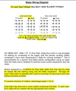
I think if you checked your motor terminations and compared to the new supplied connection diagrams you might find some differences there, and possibly an easier time getting it up to speed, with less current draw. you should be checking your current draws on all three legs while getting it up to speed.

A few pointers about selecting and using overload relays. heater elements, and phase converter supply sources. Overloads come in a few types and ratings. when using them with a RPC power source. almost all IEC (European style) units such as the Klockner Moller type you have. has a differential current protection built in. What this means is that the overload relay senses a difference of current between the three legs. When there is a difference it shifts a balance bar within the relay to cause it to trip faster to better protect the motor windings, unequal currents can heat up the motor windings much faster. The more loaded the motor is the worse this heating becomes. you already will have unequal voltages and currents with a RPC power source and its lower generated leg so its wise to be aware of this and not select an overload range that is so tight that you have no room to adjust upwards if that becomes necessary due to nuisance tripping. You don't want higher setting than necessary, just enough to bump it past a tripping point if that becomes necessary with increased loading or power imbalances. the IEC overloads typically have a class 10 rating, which is the lowest rating. Class 10 and 20 or 30 are typical of NEMA overloads and can tolerate heavier loads without tripping on short or light overloads. NEMA overload relays with separate heater elements normally lack any automatic phase balance compensation, you can do so manually by selecting different heater element sizes from each other if required.

Overloads that use bimetallic sensing elements can become UN-calibrated if they are heated up and tripped repeatedly.when this happens, they will trip faster than rated for, and new thermal elements may be required. Many IEC overloads will have two settings, one thermal for the long time setting and one magnetic trip for instantaneous short circuit currents, similar to a circuit breaker. Your Klockler Moller unit has both of these features also. Klockner Moller has been bought out by several players in the field, Eaton has a lot of their line and has redesigned many of the parts, so going forward they might not be well supported. For a heavily loaded piece of equipment run off of a RPC I would choose a NEMA starter and overload relay with individual elements. this negates the problem with class 10 thermal performance and usually gives you class 20 performance, with no magnetic trip monitoring. Individual heater elements can be sized per leg if that becomes required in your application.

I would be looking for a used NEMA Size 2 starter with a 120V coil and a set of heaters that match your motor. Make sure that it will fit in your control panel space or put it in it's own enclosure on the side of the machine. Should be a common item on ebay or other used parts supplier. I hope that helps you and good luck getting it straightened out.

For testing to see if your RPC can handle it remove the overload relay and bypass it with a set of jumpers, check to ensure that the motor connections are properly made up to the diagrams given and give it a spin, you really cant hurt a starter that is only half the size needed, i will go or it will blow, but don't keep using it that way if it runs for you or you could be looking at an expensive motor rewind.
 
Someone is owed a beer. :drink:
Tell me about it!

Thanks SAF and everyone else who has contributed so far. This is very helpful!

I think I’m following you in your last post regarding overloads...I was already looking on eBay yesterday at a few different Allen Bradley branded Nema 2 O/L, contactors that are rated for 30+ amps @ 230v.

Going back to the previous post....since I am essentially starting over with the overload / coil / etc is there value or potential in this situation to move to a Wye start -> Delta run configuration with multiple contactors, given the starting load and borderline size of my RPC relative to this motor? This will likely require a new enclosure due to size and quantity of contactors (?) and I don’t know how it will compare $$ wise on the front end, but wondering if that’s a wise move to consider.

Regarding the motor wiring diagrams and misprints, etc...that was initially throwing me for a loop when comparing with accepted 12 wire low voltage wiring patterns found online (which is how the machine came to me wired as shown in OP) Are you suggesting that the original paper Brook motor literature is to be disregarded or ?

Many thanks again and again for the clarity and taking the time to spell all this out for me.
 
I think I’m following you in your last post regarding overloads...I was already looking on eBay yesterday at a few different Allen Bradley branded Nema 2 O/L, contactors that are rated for 30+ amps @ 230v.
I use Allen Bradley but I did not buy anything brand new. The local electrical surplus places have it.
There are on-line surplus but have not dealt with any of them. I avoid ebay.
 
An additional thing I recommend you do before trying to test your motor and starter, is to relabel your 12 motor wires before you start moving them around. From the photo they looked in poor condition and likely to come off or get mixed up when disturbed. Obtain a fresh book of wire tags and replace them first thing. Especially 6 & 9 they are easily Mixed up, the numbers should be underlined for clarity. If you loose track of them while working on them will cause you some serious grief and trouble. Try to keep the tags below the wad of tape that you will use to insulate the ends of the bundles. Don’t memove the old tags until your absolutely positive that they are correctly labeled and functionally correct. You might want to assume that they could have got partially mixed up by the last guy that worked on rewiring it for the lower voltage and connecting it to the wrong starter. Be very careful and observant while making the changes
Misconnected motor leads is bad juju and serious problem trying to figure out what is wrong after the fact.
 
Tell me about it!

Thanks SAF and everyone else who has contributed so far. This is very helpful!

I think I’m following you in your last post regarding overloads...I was already looking on eBay yesterday at a few different Allen Bradley branded Nema 2 O/L, contactors that are rated for 30+ amps @ 230v.

Going back to the previous post....since I am essentially starting over with the overload / coil / etc is there value or potential in this situation to move to a Wye start -> Delta run configuration with multiple contactors, given the starting load and borderline size of my RPC relative to this motor? This will likely require a new enclosure due to size and quantity of contactors (?) and I don’t know how it will compare $$ wise on the front end, but wondering if that’s a wise move to consider.

Regarding the motor wiring diagrams and misprints, etc...that was initially throwing me for a loop when comparing with accepted 12 wire low voltage wiring patterns found online (which is how the machine came to me wired as shown in OP) Are you suggesting that the original paper Brook motor literature is to be disregarded or ?

Many thanks again and again for the clarity and taking the time to spell all this out for me.
Checking back in, since it’s been a few weeks since we last talked. Wondering if you had any time to go over the things discussed? How about bypassing the existing overload relay and trying to start the spindle on your RPC? Did you look at the 12 lead motor winding connections in the motor connection box? Did you try the alternate connections provided in the attached papers? Just wondering if you have any updates for us on your progress.
 
Checking back in, since it’s been a few weeks since we last talked. Wondering if you had any time to go over the things discussed? How about bypassing the existing overload relay and trying to start the spindle on your RPC? Did you look at the 12 lead motor winding connections in the motor connection box? Did you try the alternate connections provided in the attached papers? Just wondering if you have any updates for us on your progress.
Thank you for checking in. I think I have it sorted. A couple of days ago I received a larger Klockner Moeller overload relay (ZM-32 that fits the existing contactor) that I ordered online to replace the existing ZM-16 (16 amp) that was tripping. I wired it in and everything seems to start and run fine now with the overload amps set to ~30.

The RPC seems to be able to handle the start load fine, though I have not had the chance yet to test with tooling on the spindle or use it to make any wood chips yet.

I also have some new motor lead labeling tags on the way, so thank you for that suggestion.


Back
Top