What's new
What's new

Hendey Tool & Gage Restoration

I don't grok that? "Tapered" how and why?

Can you enlighten?

Here's a photo. Any shim or build-up between the base and the body will prevent it from seating fully.
 

Attachments

  • IMG_3323.jpg
    IMG_3323.jpg
    88.3 KB · Views: 154
  • IMG_3324.jpg
    IMG_3324.jpg
    88.3 KB · Views: 151
Here's a photo. Any shim or build-up between the base and the body will prevent it from seating fully.

Got it now.

Most I have seen were square-sided ribs.

"School solution" is to alter it ...and add a gib?

PITA. So is carving a new base from Iron that needs no shim.

Least work to Turcite/Moglice the BOTTOM?

ELSE ...

Clean-up the bottom. OEM style Iron sliding on Iron.

Accept a drop.

Then over-bore the upper, eccentric to OEM CL.

Fab a new ram

Line bore in situ?

Which .. also fully corrects for ram and bore and clamping wear. Advancing screw and anti-rotation keying, too.

I don't think worrying about "interchangeable parts" to factory OEM spares, Eli Whitney-style.. makes a damn at this late stage? Not even with Hendeyman doing his usual "magic."

:D

Even if.. a "less worn" TS could be found from a (rare) part-out, it would still need much the same process applied?
 
Joe you could mill a pocket to accept a small piece of durabar that gets screwed in and remachine the taper to play nice with the new shimmed height. For the saddle you could also screw in some thin durabar strips (even make the screws from same matl) and scrape to your new height. It's a good deal of work but would probably be better than scraping the headstock and trying to lower the gearbox and associated parts.

Or have you a good foundry nearby? Build up your saddle and tailstock base, have new casting poured then machine them to your newly scraped bed. That's probably closer to what Hendey might have done if you sent a lathe in for rebuild? I don't think there are really any other good options to maintain the metal on metal you're seeking to achieve.
 
If it was mine I would shim it to the correct height. Bolt down and use feeler gauges to determine how much clearance to make up, probably on the vertical edge.You can buy 12" feeler strip pretty much any thickness in .001" increments.
To fix the shim in place quickly just bend the ends 90. If that is not desirable then drill a couple holes in the new gib shim and matching shallow holes in the key wall insert a few roll pins or brass rod to keep the gib in place and cut to length and it will not be seen.

Remember this is not a working joint like any other slides. Unless you are continusly turning tapers you may only move it once a year.
 
Over 6 months later and I'm finally done with the tailstock ways. Scraping isn't THAT slow, I just haven't had much time to spend in the workshop. I've put 60, maybe 80 hours into it.

The T&G has an unusual tailstock way geometry. Now that I've scraped it, I will say that I don't like it, I think it's inferior to the "normal" geometry. The problem is that as the angled surfaces wear, the tailstock will develop a lateral slop, which will result in taper.

My master is a 48" camelback that I acquired from a pro rebuilder and scraped in myself. It's a really nice straight edge. I used a small 8x12 surface plate to get the adjacent flats coplanar. After I roughed the flats down, I used the tailstock base itself to set the angles on the angled ways. There was a lot of back and forth, getting perfect parallelism between the angled ways, and the perfect spacing to fit the tailstock base.
 

Attachments

  • IMG_3452.jpg
    IMG_3452.jpg
    93.8 KB · Views: 167
  • IMG_2211.jpg
    IMG_2211.jpg
    89.8 KB · Views: 149
  • IMG_2212 2.jpg
    IMG_2212 2.jpg
    94.4 KB · Views: 154
  • IMG_3466.jpg
    IMG_3466.jpg
    96.8 KB · Views: 161
Re-cutting V-slides on a saddle is easier said than done. It's difficult to find a place to clamp it to the table, and do so without causing any distortion. Plus the saddle is awkwardly large compared to a normal mill table. I had a hell of a time with my South Bend, and I've been planning this ever since.

To start with, I leveled the saddle upside-down on my surface plate, and chose three through-holes to use as support points. The rear slide only has one through-hole, and it is not centered, but I wasn't too worried as I planned to take light cuts. Next I built a fixture out of 2" square tubing, and mounted it on the Bridgeport table. I leveled it with shims, leveling to the apron mounting surface in X and the top of the dovetail in Y. The rear of the saddle is a nice factory-scraped surface, which I used for tramming. I verified level and tram by measuring pin gages set in the V-slides. Leveling and tramming was the hardest part, it took a few hours.

IMG_3503.jpg
IMG_3502.jpg
IMG_3500.jpg

With the Bridgeport head nodding down 45º, there wasn't enough travel on the table to reach both slides in the same setup. It was a bit awkward but I was able to use my right-angle head to get a little more reach. Light cuts... it worked fine. I cut the relief in the V a little deeper too.

IMG_3518.jpg
IMG_3521.jpg

Took some measurements on the surface plate and the slides are co-planar within .001". Not bad for an old Bridgie. I did a few rounds of scraping, and I have started using it as a angle / spacing master while I rough in the bed. As the bed comes in, I will finish scraping in the saddle to get perfect parallelism.
 
Much the same approach I took with My T&G.
I did find that the surface where the apron attaches, warped a couple of thou and caused some binding when I assembled the machine. Some scraping and a thin shim fixed that issue.

Keep up the great work!
Pete
 
I did find that the surface where the apron attaches, warped a couple of thou and caused some binding when I assembled the machine. Some scraping and a thin shim fixed that issue.

I have the same issue, it's about .004 concave. I'll have to address it before I'm done, or my nicely scraped slides will distort when assembled. I think I'll do it on the mill, when I fit the rear gib.
 
Progress: carriage ways are done.

I started off blind scraping using just an indicator mounted on the tailstock base. Even just scraping by hand it's possible to remove material quickly. I did the front first and then the rear, using the rough-scraped saddle as a gauge to get the spacing correct. Once I was through the wear and had them about the same height, I blued the saddle and used it as a master to get the angles correct. Then I went back to the camelback, focusing on straightness and parallelism. When the ways were almost done, I went the other way and used the ways as a master to finish-scrape the saddle. I did a few more passes on the ways and they are looking great.

I was annoyed by the concave base of the level one too many times, so I scraped that too. I think flat is better for this kind of work, it reliably repeats to .0001 now. Still, twist in the bed is hard to measure. I thought I had it perfect, and I just measured again and found .0002 of twist. It may be because I had the door open this morning and caused a temperature differential.
 

Attachments

  • IMG_3481.jpg
    IMG_3481.jpg
    87.7 KB · Views: 118
  • IMG_3697.jpg
    IMG_3697.jpg
    97.1 KB · Views: 114
  • IMG_3714.jpg
    IMG_3714.jpg
    93.1 KB · Views: 113
  • IMG_3718.jpg
    IMG_3718.jpg
    95.1 KB · Views: 116
  • IMG_3713.jpg
    IMG_3713.jpg
    83.6 KB · Views: 114
The saddle and cross slide are done. After scraping the saddle V-slides I set it up on the mill again to cut the cross slide ways. This time I didn't have to shim anything, just rested it on three matched gage pins on setup blocks, as close as possible to the clamp points. Before cutting, I measured squareness of the dovetail to the bed ways, and found it surprisingly very close to square. So when I set it up on the mill, I trammed it to a precision rod in the dovetail. And I didn't cut the angled surfaces, just the flat and a relief in the corner.
IMG_3860.jpg

IMG_3876.jpg

I scraped the cross slide ways using my small straight edge as a master, measuring parallelism to the V-slides on the surface plate. After it started coming in, I also used the scraped cross-slide as a master.
IMG_3904.jpg

Next was the non-gibbed dovetail. While roughing I just used a machinists square to measure squareness, but for the final stages I upgraded to my scraped 45-45-90 master. This tool is a joy to use, I wish I had more reasons to use it.
IMG_3916.jpg

There was not enough clearance for a micrometer to measure parallelism of the dovetail ways. So I used a surface gage pressed up against a gage pin, and rocked it downwards to measure the high spot on the opposing gage pin. It worked ok, it repeated within a tenths which I think is not quite as good as a micrometer.
IMG_3925.jpg
 
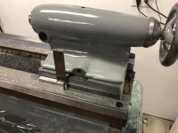
Lots of progress on the lathe lately, but most of the projects are unfinished so there's not much to report. But I did get the apron mounted, and I measured the total drop WRT the lead screw.

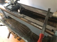
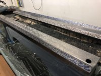
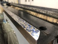
When I scraped the slides on the saddle, I had noticed that the apron mounting surface was about .005" concave. That's too much to ignore, or as soon as I tighten the apron mounting screws the front slide will distort convex. So I milled this surface down and scraped it flat. I didn't aim for perfect coverage because I really didn't want to remove too much material, or else I would have to adjust the gearing. The mating surface on the apron was in better shape than the saddle, but it needed a few cycles too.
IMG_4083 2.jpg

After scraping I test-fit with the gears installed, it felt fine and there's still a little backlash. No adjustment needed.
IMG_4084.jpg

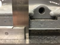
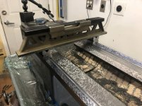
Next I cut new bearings for the drive rod and got it installed. I measured the distance from the apron mounting surface with an indicator on a magnet base.

For the apron, I pressed an expanding mandrel into the worm carrier for the drive rod. I set the apron upside down on a surface plate, and used the same indicator setup to measure the height to the mandrel. The difference, plus the radius of the rod/mandrel gave me the total drop of the apron: .030".

IMG_4153.jpg
IMG_4152.jpg

I've already decided against building up the saddle slides with turcite, etc. My plan at the moment is to repin the gear-box and leadscrew support, I'll make some offset pins and enlarge the screw holes.

But while I was scraping the apron mounting surface I was thinking about adjusting the gearing, and I don't think it would be too hard. And I started thinking that instead of repinning the gear box, I could raise the apron instead by removing that .030" from the saddle and adjusting the gearing. The idler gear is a DP28, so I could cut a new gear with one less tooth for a diameter reduction of .035". I'd have to move the gear too. I think it's doable, maybe a little harder than repinning but the result might be cleaner. I'm considering it.
 
The rear gib way was out about .010". It's a really uncomfortable position to scrape! So I rigged up this arrangement with a boring bar, used the tailstock base as a sled, and planed it by hand. Not the most rigid setup but I took light cuts and it worked great. I scraped out the tool marks and then rough scraped about a dozen more cycles. For the gib way I think this is good enough.

IMG_4097.jpg
IMG_4162.jpg
 
I finished fitting the rear gib. I started by milling .042 off of the saddle at the rear gib attachment point, then scraped it flat. I got it perfect, clearance of .001".

IMG_4190.jpg
IMG_4191.jpg

When I had previously test-fit the lead screw, I wasn't happy with the fitment. The bearings were sloppy, and both the screw and rod were obviously bent, they were both binding during rotation. The first thing was to scrape the bearing support, this surface had some wear from the bearing flanges.
IMG_4196.jpg

I filed/polished the wear out of the shaft/gear on the left. Then I installed new bronze bearings in the support, then bored them to fit. The bronze bearing (center) was pretty worn, I faced it and bored it slightly larger, then cut a new sleeve (right) to fit.
IMG_4238.jpg

The drive rod and screw were both bent, the drive rod pretty bad with TIR=.030". I measured the high spot on V-blocks, and straightened it on a press, I got them both within straight a few thousandths. I got it all reassembed, it fits perfectly and turns so smoothly.
IMG_4246.jpg

Next is the tailstock. Still trying to find someone to hone it.


Back
Top