What's new
What's new

Hick Hargreaves Engines

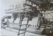
I remembered that I have a book called 'River-class Frigates and the Battle of the Atlantic', by Brian Lavery. The ships were designed in haste during the winter of 1940/1. They were simple and uncomfortable. There's a photo of one of the four-cylinder triple-expansion engines, and I was amazed to see that it is almost identical to the one in the last photo in post #35!

I won't copy the photo from the book, but the only noticable difference is that it doesn't have the crankcase splash guards seen on Billmac's photo. However, here they are in this 1943 photo! :-

INTERIOR STUDIES ON BOARD A FRIGATE. 5 JULY 1943, ON BOARD THE RIVER CLASS FRIGATE, HMS MOURNE, AT LIVERPOOL. | Imperial War Museums

I rest my case!

Those things on the side are lubricators, by the way.

Billmac's photo is clearly taken in a dark shop, so it is consistent with wartime blackout.

I wasn't satisfied about the dates of the other photos, though, which weren't in a blacked-out shop. By another stroke of luck, I've found that Hick's had made a three-cylinder triple-expansion engine for the Ministry of War Transport, for a "C Type" wartime standard cargo ship, built by the Shipbuilding Corporation in Newcastle in 1947 and launched as the 'Empire Birdsay'. Later renamed SS Lokoja Palm, then various other names, and scrapped in 1971.

Zarian 1947

On edit: In 1944 they supplied a three-cylinder triple-expansion engine for the Ministry of War Transport's 'Empire Grey' (Readhead & Sons Ltd, South Shields).

Empire Grey 1944

Not only that but they look just like “ T&K “ lubricators. The glass tubes were filled with glycerine if I remember rightly and you could see the lubricating oil slowly making its way up the outside of a copper wire that was in the middle of the glass tube.

Regards Tyrone.
 
When I noticed Asquith's links and the Tyne Built Ships site I was reminded of this story I had heard on TV a few years ago .
Sting talks about his new musical "The Last Ship" - YouTube
Even though it is from an earlier time I checked to see if the engine of the Acadia mentioned in the video might have been a Hick Hargraves but it wasn't so I hope this doesn't run this thread too far off track .
Acadia 1913
Unfortunately they don't show the engine room in the video.
but there is one picture on this page
THE ACADIA IS SAVED! - Charles Douglas Maginley, 1929-2020
and another one here ,
CSS Acadia
More about the ship here
CSS Acadia | Maritime Museum of the Atlantic
https://www.google.ca/search?q=C.S.....5#imgrc=7h5eCGx-TveTnM&imgdii=mrXY4vLAbh_fiM
Jim
 
Only a small % of glycerine is enough to stop the water freezing and reduce the tendency of the water to form an emulsion with the lighter fraction of the oil.
 
Only a small % of glycerine is enough to stop the water freezing and reduce the tendency of the water to form an emulsion with the lighter fraction of the oil.

I can’t remember just what the percentage of glycerine was now, it’s quite a while ago since I worked on those pumps. They had a lever on the front of the pump that you could toggle the flow of oil with to get it started. The oil would work it’s way up the wire like a snake charmer’s snake.

Regards Tyrone.
 
Asquith mentioned (post #25) the old blast injection Hick, Hargreaves diesel engines which were still on standby at Hampton Pumping Station, London in 1971.

I have attached the photo, taken from Stationary Steam Engines of Great Britain, Volume 8. (Ten volumes of photos taken by George Watkins from the 1930's through to the 1970's, mostly of working engines).

I see there are crankcase covers fitted between the A-frames, maybe a later fitting?


Hick, Hargreaves diesel engines at Hampton Pumping Station, George Watkins 1971 photo.jpg Hick, Hargreaves diesel engines at Hampton Pumping Station, George Watkins 1971 photo 02.jpg
 
While billmac is sorting through the dusty archives....I hope he doesn't mind if I include a few Hick, Hargreaves engines?

This photo comes from The Textile Mill Engine, Volume 1 by George Watkins, a mind-blowing series of big engine photos.

This Hick, Hargreaves engine is old - 1877. It powered a cotton spinning mill for 50 years as a single cylinder engine, 39.75" bore & 8 ft stroke (!) Then a 22" cylinder was added to make it a tandem compound engine developing 1,000 hp at 57 rpm. It ran like this until 1960.

Note the 'American style' flat belts, 45" and 38" wide.

Hick, Hargreaves 1877 Crosses & Winkworth, Rose Hill No. 3 Mill, Bolton 01.jpg Hick, Hargreaves 1877 Crosses & Winkworth, Rose Hill No. 3 Mill, Bolton 02.jpg
 
While billmac is sorting through the dusty archives....I hope he doesn't mind if I include a few Hick, Hargreaves engines?

This photo comes from The Textile Mill Engine, Volume 1 by George Watkins, a mind-blowing series of big engine photos.

This Hick, Hargreaves engine is old - 1877. It powered a cotton spinning mill for 50 years as a single cylinder engine, 39.75" bore & 8 ft stroke (!) Then a 22" cylinder was added to make it a tandem compound engine developing 1,000 hp at 57 rpm. It ran like this until 1960.

Note the 'American style' flat belts, 45" and 38" wide.

View attachment 347101 View attachment 347102

There was a cotton mill on every street corner when I was growing up in Rochdale. I suppose they would all have had a mill engine when they were first built. They’ve nearly all gone now. What was a forest of mill chimneys is now down to one or two. At least we don’t have the smogs that came with them any more.

Regards Tyrone.
 
Going back to marine engines, in post #30 I mentioned some of the company’s early marine engines. In fact they were made by Benjamin Hick & Son (the name of the company before it became Hick, Hargreaves). One of the ships, the Brazilian frigate Dom Afonso, was built in Liverpool in 1847. On its maiden voyage it went to the rescue of a blazing American ship carrying emigrants from England to Boston. The Brazilian crew were handsomely rewarded, but they gave the money to the survivors, who had lost everything. Translated Wikipedia entry here:-

Dom Afonso (fragata) – Wikipedia, a enciclopedia livre


Going back to the photos of more modern marine engines made by Hick, Hargreaves, shown in posts #31 & 36, three types of engine are shown. One is for a River-class frigate. The role of the others has not been identified. One type has a mix of box-section and cylindrical columns supporting the cylinders. The other has all box-section columns.

We know that Hick, Hargreaves made engines for the Empire Grey (1944) and Empire Birdsay (1947). These were "C Type" wartime standard cargo ships. The first of the class was the Empire Liberty, 1941, built by Joseph L Thompson & Sons. They were also built in Canada and, I think, Australia. The British Government ordered ships from the USA based on the design of this ship, the first US-built example being the Ocean Vanguard. The type was developed in the USA as the Liberty Ship.

The engines were 3-cylinder triple expansion with cylinders of 48" stroke and bores of 24”, 39” and 68” or thereabouts, originally designed by the North Eastern Marine Engineering Co. They had box-section engine columns, so the engine in post #36 may have been for one of these Empire ships.

That leaves the engines with the round columns unaccounted for.

Incidentally, a good source of information on the Liberty Ships is Workhorse of the Fleet - A history of the design and experiences of the Liberty Ships built by American Shipbuilders during WWII by Gus Bourneuf Jr.

Online here:-

https://ww2.eagle.org/content/dam/eagle/publications/company-information/workhorse-of-the-fleet-2019.pdf
 
Last edited:
Here are a couple more big Hick, Hargreaves engines used in the textile industry.

1923 cross compound engine with drop valves, 1,850hp, steam at 160psi, superheated.
Note racks on the floor to enable the cylinder covers to be cranked out of the way for repair work.

Hick, Hargreaves cross compound at Mutual Mills, Heywood No. 3 Mill 01.jpg Hick, Hargreaves cross compound at Mutual Mills, Heywood No. 3 Mill 02.jpg


1915 cross compound engine with Corliss valves, 2,000hp, 65 rpm, steam at 180psi. Cylinders 30" & 60" bore x 5' stroke.
25' flywheel with 46 ropes.

Hick, Hargreaves at Horrocks, Crewdson & Co., Preston 01.jpg Hick, Hargreaves at Horrocks, Crewdson & Co., Preston 02.jpg

The book these images came from:

The Textile Mill Engine Vol 2 by George Watkins, cover.jpg
 
This link shows the top of a triple expansion engine being lowered into one of the Thompson Designed cargo ships mentioned by Asquith built in North Vancouver in WW2 .
They mention that this engine was built by Dominion Engineering from Montreal and other locations in Canada .
North Vancouver's Wartime Shipbuilding - Lowering Engine - MONOVA
There are more pictures if you scroll down .
More related links I looked at here suggest that the engines were built by other Canadian companies including Canadian Vickers
Dominion Engineering is not mentioned anywhere else that I have seen .
Park ship - Wikipedia.
The ‘Park’ and ‘Fort’ ships - History and culture
A photo here of the engines from an American Liberty Ship
Compound steam engine - Wikipedia
I've also seen pictures of marine engines built by the Collingwood Ship Yards on the Great Lakes
This is an older article about that yard from 1911.
Canadian machinery and metalworking : Free Download, Borrow, and Streaming : Internet Archive
I'm wondering if this is the one of the same Lubricators mentioned by Tyrone ?
https://ingeniumcanada.org/sites/de...nsion-steam-engine-gallery1.jpg?itok=YRB8Jpr6
It is on a preserved triple expansion engine built by Canadian Vickers for a smaller ship
https://ingeniumcanada.org/scitech/artifact/canadian-vickers-ltd-triple-expansion-steam-engine

No Jim,they aren’t “ T&K “ lubricators. The lid of the sump in the foreground seems to say “ Tecalamit “, they were makers of lubrication equipment.

Regards Tyrone.
 
Going back to post #46, showing a George Watkins photo of a large mill engine with leather belts, I was curious about the smallish rope drive wheel visible in the photo. I remain puzzled, but I did notice something in another George Watkins book, The Steam Engine in Industry – Mining and the Metal Trades. It shows a c.1925 uniflow rolling mill engine at Abercarn tinplate works, and GW mentions a rope drive to a Hick-Breguet condenser below. A small diameter wheel is just visible on the crankshaft with grooves for half a dozen ropes. I don’t know anything about Hick-Breguet condensers, but I presume that the Abercarn one had a mechanical air pump? So, I wonder whether the 3-rope wheel in post #46 could drive a condenser air pump? I have my doubts, as the wheel in that photo has a series of holes in the rim, such as you might find in an engine flywheel, not in an idler pulley.

My own involvement with Hick, Hargeaves equipment is limited to ancillary plant in various power stations. Some of this was condenser related - air extraction plant - which included liquid ring pumps and ejectors. It was trouble-free, so didn't attract any attention. They also undertook condenser retubing work (replacing tens of thousands of copper alloy tubes with titanium).

I also came across feedheater pressure vessels made by Hick, Hargreaves in the 1960s under subcontract. Similar vessels in the same system had been made by another ex-mill engine maker, Foster, Yates and Thom of Blackburn, and were not the finest examples of the fabricator’s art.

Foster, Yates & Thom, previously just Yates & Thom, had made some very fine engines. It was they who’d added the high pressure cylinder to the Hick Hargreaves engine in post #46.

I also found that Foster, Yates & Thom had made at least one of the WW2 triple expansion engines, for the Empire Clough.

Another Lancashire firm making marine engines for the Ministry of War Transport in WW2 was Walker Bros of Wigan.

I was also interested to see that another of those standard triple-expansion engines was made by Canadian Allis-Chalmers of Montreal, not for installation in Canada, but for the Empire Prospect, built in Newcastle.
 
Here is a link showing the Canadian Allis Chalmers Plant after a fire in 1911 ,
Accueil | BAnQ numerique
I posted some more links about it in Post # 3 of this thread .
https://www.practicalmachinist.com/...-chalmers-co-383712/?highlight=Allis+Chalmers
Canadian Vickers was also mentioned as a builder of the triple expansion engines .
Here are a some links about that plant from earlier times.
Canadian Shipping and Marine Engineering January-December 1915 : Free Download, Borrow, and Streaming : Internet Archive
Canadian Shipping and Marine Engineering January-December 1914 : Free Download, Borrow, and Streaming : Internet Archive
Accueil | BAnQ numerique
This one from about 1927
https://numerique.banq.qc.ca/patrimoine/details/52327/3138501
As found here
https://numerique.banq.qc.ca/recher...se/P/desc/W10=/Liste de résultats/true/false/
Articles from the WW2 time period and not as available on line as earlier ones .
Jim
 
Last edited:
Going back to post #46, showing a George Watkins photo of a large mill engine with leather belts, I was curious about the smallish rope drive wheel visible in the photo. I remain puzzled, but I did notice something in another George Watkins book, The Steam Engine in Industry – Mining and the Metal Trades. It shows a c.1925 uniflow rolling mill engine at Abercarn tinplate works, and GW mentions a rope drive to a Hick-Breguet condenser below. A small diameter wheel is just visible on the crankshaft with grooves for half a dozen ropes. I don’t know anything about Hick-Breguet condensers, but I presume that the Abercarn one had a mechanical air pump? So, I wonder whether the 3-rope wheel in post #46 could drive a condenser air pump? I have my doubts, as the wheel in that photo has a series of holes in the rim, such as you might find in an engine flywheel, not in an idler pulley.

My own involvement with Hick, Hargeaves equipment is limited to ancillary plant in various power stations. Some of this was condenser related - air extraction plant - which included liquid ring pumps and ejectors. It was trouble-free, so didn't attract any attention. They also undertook condenser retubing work (replacing tens of thousands of copper alloy tubes with titanium).

I also came across feedheater pressure vessels made by Hick, Hargreaves in the 1960s under subcontract. Similar vessels in the same system had been made by another ex-mill engine maker, Foster, Yates and Thom of Blackburn, and were not the finest examples of the fabricator’s art.

Foster, Yates & Thom, previously just Yates & Thom, had made some very fine engines. It was they who’d added the high pressure cylinder to the Hick Hargreaves engine in post #46.

I also found that Foster, Yates & Thom had made at least one of the WW2 triple expansion engines, for the Empire Clough.

Another Lancashire firm making marine engines for the Ministry of War Transport in WW2 was Walker Bros of Wigan.

I was also interested to see that another of those standard triple-expansion engines was made by Canadian Allis-Chalmers of Montreal, not for installation in Canada, but for the Empire Prospect, built in Newcastle.

I may have told this story before Asquith but about 30 years ago I had to go over to the old “ Foster, Yates & Thom” factory in Blackburn to supervise the loading of some machinery that was being exported. “ Foster,Yates & Thom “ had closed years ago. The factory had been taken over by a company that packed and exported machinery.

It was an old style engineering works with the usual overhead cranes. A huge “ Craven “ planer was being prepared for export to the third world.

What sticks in my mind was a chat a had with one of the young employees. Just to make conversation I asked him how much he was earning, as you do when engineers chat. The lad said “ About 80 pints a week “.

Regards Tyrone.
 
My own involvement with Hick, Hargeaves equipment is limited to ancillary plant in various power stations. Some of this was condenser related - air extraction plant - which included liquid ring pumps and ejectors. It was trouble-free, so didn't attract any attention. They also undertook condenser retubing work (replacing tens of thousands of copper alloy tubes with titanium).

One of our volunteer team carried out 'outside' work like this for Hick Hargreaves. He fitted Titanium tubes to condensers all over UK, mostly in power generation. You may well have run into him. He has a lot of stories to tell about these jobs.
 
Bill,

I didn’t get involved with condenser retubing, but I do know that replacing ‘brass’ tubes with titanium introduced a problem. Titanium wasn’t such a good conductor of heat, but the tubes could be made much thinner to compensate. However the much thinner and lighter titanium tubes had very different vibration characteristics, which were not compatible with the original sagging plate spacing. It wasn’t practicable to alter the sagging plate positions, so Hick Hargreaves addressed the problem in an ingenious way. They installed flattened rubber tubes at intervals between the titanium tubes. These were flattened by evacuating the air from within, and sealing the ends. When all was ready, the ends were unsealed and the rubber tubes expanded, pressing against the titanium tubes, and providing excellent vibration damping. Or something like that.
 
Asquith,

Thanks for the book/pdf link you provided about the Liberty ships, good stuff.

-------

I'm not clear about the various war time cargo ships and their engines - e.g would the Hick, Hargreaves-built engines be the same as the Liberty engines.

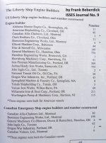
Here is a list of the Liberty engine builders, both USA and Canada.

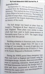
This comes from ISSES Journal No. 9 which had a good paper on the Liberty engines, written by Frank Beberdick.

The author indicates the same engine design was used in Britain as well as Canada and the USA.


Liberty Ship Engine Builders ex-ISSES Journal No 9 01.jpg Liberty Ship Engine Builders ex-ISSES Journal No 9 02.jpg
 
The Gus Bourneuf Jr book pdf that Asquith linked to (post # 49) indicates the "Liberty" crankshafts were either built-up (the majority were) or one piece, but had to be interchangeable (as did all the parts, regardless of the manufacturer). He says the built-up crankshafts were assembled in jigs to aid this requirement.

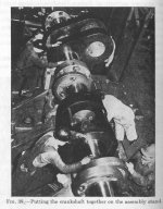
I have a book titled Standard and Emergency Shop Methods by Colvin & Stanley, first published in 1945 though I have a Lindsay reprint.

I don't think the book actually states these photos show Liberty engine parts, but I am sure they are.

The photos are from the Joshua Hendy Ironworks with a brief description of the methods.

Note, the "Emergency" part in the book title refers to using machine tools in perhaps novel ways, simply because that was all that was available at the time (that time being WW2). There are re-purposed lathes, mills, drilling machines etc. being used to "get it done".

For example this boring mill set-up. Those crank webs are not small - 1600lbs each (726kg).

And some good info on shrink fits, temperatures etc. used for the crankshaft assembly.

Shop Methods pg 140 edit.jpg Shop Methods pgs 140-141.jpg Shop Methods pgs 142-143.jpg Shop Methods pgs 142 edit.jpg
 
Peter,

Thanks for the information.

Gus Bourneuf Jr states that the General Machinery Corp. of Hamilton, Ohio built 60 main engines in 1941 alone. ‘The engine was designed by the North Eastern Marine Co., a division of Richardson, Westgarth & Co., Ltd., Wallsend-on-Tyne. Here again it was found necessary to redraw the plans. British marine engine builders and other manufacturers in general leave many details of the drawings to shop practice – an arrangement which worked well when the staff grew up on the job, and where the whole unit is usually cast, machined, assembled, erected and installed under one roof. For example the designer did not put down clearances between crankshaft and bearings contrary to American practice. For US conditions however, it was necessary to amplify and redimension the British plans with respect to tolerances, fits and clearances, degree of finish, fillets, etc., and also certain other modifications to meet US standard flanges and fittings. Apart from these items and the use of US threads, wrench sizes, etc., the main engine design followed the British parent design. Also the British practice was to include many items on the one drawing and it was necessary to break these down into single item plans. …..’

Most of the engines made in the UK came from a variety of marine engine builders, and I’ve only found isolated examples from non-marine engine specialists. I note from your table that several of the US and Canadian builders also made just a handful of the engines. It seems wasteful to have got those firms to gear up just to make a few engines. In the case of Hick, Hargreaves, I’d be surprised if they’d had any recent experience of constructing complete reciprocating engines.


Back
Top