What's new
What's new

Hilger & Watts TA51-2 autocollimator

ballen

Diamond
Joined
Sep 25, 2011
Location
Garbsen, Germany
I stumbled across a Hilger and Watts TA51-2 two-axis autocollimator in (what appears to be, based on photos) good condition. The price was reasonable, so I bought it. I'm starting a thread here to gather some info and to document any repairs or issues. I have not received it yet, but here's a photo from the seller. It has what appears to be an internal calibration sticker, dated July 1990, from Siemens, and is in the original wooden storage box, so I'm optimistic that it's not damaged beyond repair. Fingers crossed.

Screenshot 2022-12-20 at 06.35.47.png

The autocollimator is still in production at Taylor and Hobson, which is now owned by Ametek. They sent me a manual (both the original manual and a recent version, which appear identical, apart from part numbers for the accessories). I have attached the spec sheet below. The autocollimator is described in sales literature as a "universal" model. It has 0.2 arcsecond divisions on the dials, a 2 1/4 inch barrel, and is claimed to be usable over a distance of 30m. The downside of these universal models is that they are larger and heavier than the "skinny barrel" one axis models, which have a shorter working range, but can also use smaller mirrors.

A few questions for the group:

- I need to make a reflector. The specs below call for a 2-inch diameter mirror flat to 3 microinches, which is 0.076 microns. Since the wavelength of green light is about 0.540 microns, this flatness is 0.14 ~ 1/7 of a wavelength. So I need a 2-inch silvered or aluminised front surface mirror which is flat to lambda/7. A quick look in catalogs shows that lambda/10 mirrors cost about 100 Euros each, new, from Thorlabs. Does anyone have a less expensive source?

- I can easily machine a cast-iron sled to hold the mirror. What's the best way to attach the mirror? Normally I'd glue it on with epoxy, but I'm concerned that this will distort the mirror and I'll lose the flatness.

- The eyepiece is on the top, but in the photos and documents I have looked at, the eyepiece is normally at the back. Has this unit been mis-assembled, and someone put the lamphouse on the back instead of on the top? Or is this a special top-reading model (maybe that's the "-2" in the model number)? Or can one swap the eyepiece to either location and use the autocollimator in either configuration?

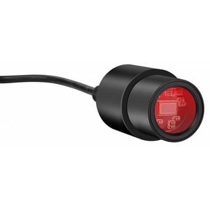
- I would like to fix an inexpensive USB camera to the eyepiece so that I can view the image full screen on a laptop. Has anyone done this? Pointers/advice would be welcome.

Cheers,
Bruce

PS: if anyone is eager to get one of these for themselves, there is one for sale on Ebay located in in Arcadia, California USA. It is lacking the adjustable three-point base, and the asking price ($700) is substantially more than I paid, so it could probably be negotiated down. I just noticed that it also has the eyepiece on top not on the back, so perhaps this configuration is common and not unusual.


Screenshot 2022-12-20 at 06.16.44.png
 
Last edited:
I have the same model. You can turn the instrument in its fixture after loosening the two knurled screws you see on top. No concerns about glueing a mirror, if you use a mild shoe-sole glue instead of epoxy. I have already employed slip gauges for mirroring in tight places like exposure apertures of cameras and the like. For aligning machine tools your mirror holder should have a good base so it can stand alone.
 
I have the same model.
Thanks for the quick reply -- nice to have another owner here!
You can turn the instrument in its fixture after loosening the two knurled screws you see on top.
I was asking about moving the eyepiece to the back. Turning doesn't do that. Are there two models, TA51 with the eyepiece on the back, and TA51-2 with the eyepiece on the side?
No concerns about glueing a mirror, if you use a mild shoe-sole glue instead of epoxy.
OK. Do you mean contact cement, the sort where each surface gets a thin layer, you let them dry, then just touch them together? Can you recommend a specific brand? (Wir sind beide in Deutschland, oder bist Du in der Schweiz?)
For aligning machine tools your mirror holder should have a good base so it can stand alone.
Yup, that's my plan, I'll make a solid cast base.

Thanks again for the helpful reply!

Cheers,
Bruce

PS: Google found this on mounting methods. Not quite enough detail for me to know what to use and do, however. https://wp.optics.arizona.edu/optomech/wp-content/uploads/sites/53/2016/12/Tutorial_Talbot_Jared.pdf
 
Last edited:
Ja, Äsch ist südlich von Basel.

I see what you mean with the ocular. The difference between the models is unknown to me. Be a little patient and start to use your instrument. You’ll learn about it. I always wanted to use mine vertically but still don’t have a corresponding setup.
 
Be a little patient and start to use your instrument. You’ll learn about it.
Sure, but I need to get a reflector in place before I can do anything with it.
I always wanted to use mine vertically but still don’t have a corresponding setup.
What do you mean by "using it vertically"? Is this about the ocular location? Or the orientation of the barrel?
I'd still be happy to get some specific recommendation for the glue type.
 
Vertical, ahm, let me see how I can explain that, the main tube perpendicular to the work bench and above it so that I can peep in sitting on a chair?
 
Mit dem Okular an der Spitze... Did i get that right? It's been a while, :D

I always thought it would be nice to stick a camera in the eyepiece of such an instrument. I'd like to eventually get one for my theodolite.
 
Mit dem Okular an der Spitze... Did i get that right? It's been a while, :D
(y)
I always thought it would be nice to stick a camera in the eyepiece of such an instrument. I'd like to eventually get one for my theodolite.
These days small USB cameras (endoscopes, other types) cost 10 or 20 bucks. It should be possible to adapt one for this purpose. Hopefully someone here has already done this and can report. It must be the same as for a microscope.
 
I got a spotting scope camera for mine on amazon. Haven't been able to view image on notebook yet but phone works fine. It is a back saver.

I found some davidson parallel mirrors that are super nice. You just spin them around to check perpendicularity. They are in adjustable mounts with 3 ball plungers on one side opposed by ball-tipped thumbscrews. I also found a mirror base, non-adjustable single sided but no mirror in it.
 
I got a spotting scope camera for mine on amazon. Haven't been able to view image on notebook yet but phone works fine. It is a back saver.
Sounds like just the right thing? Photo and/or part number, please?

EDIT: I just googled around and found this... it's encouraging:

I found some davidson parallel mirrors that are super nice. You just spin them around to check perpendicularity. They are in adjustable mounts with 3 ball plungers on one side opposed by ball-tipped thumbscrews. I also found a mirror base, non-adjustable single sided but no mirror in it.
Perhaps there is some nice piece of Euro-kit that you'd like to trade for? Or some cash? Just asking... if so please send me a PM.

Cheers,
Bruce
 
EDIT: I just googled around and found this... it's encouraging:
That may be a better/easier deal than i got. Mine is wifi but as i said i can't get it to talk to a pc through android emulator yet.

SME WiFi Spotting Scope Camera https://a.co/d/2w4AJni

Perhaps there is some nice piece of Euro-kit that you'd like to trade for? Or some cash? Just asking... if so please send me a PM.
PM incoming.
 
I'd consider the right-angle eyepiece to be a bonus for most work, not a drawback.

It's usually easier to "find" a large mirror, but small mirrors work. The smaller mirror may need a higher-intensity lamp in the autocollimator, and it's often necessary to block light coming from behind the mirror. I've successfully used a 8 millimeter diameter autocollimation mirror at a distance of nearly 30 feet, using a Kern DKM-2AC theodolite (bright-line autocollimation, not bright-field), by dimming the room lights and running the autocollimation lamp at 7 1/2 volts, 25% over its rated voltage.

Historically, gluing an autocollimation mirror into its holder / frame has been considered a poor practice; good practice was considered to be mechanical clamping through cork pads on both sides of the mirror itself. BUT there are times when the autocollimation mirror needs to be attached to an object so securely that it remains stationary with respect to that object through dynamics testing greater than what is expected to occur during launch into earth orbit.

Little mirrors are preferred -- simply because of their lower mass -- and glue is a lot less massive than a mechanical clamping system. That said, if significant temperature excursion is expected, the mirror substrate should have a thermal coefficient of expansion similar to what it will be attached to. Typical adhesives would include old-fashion dental cement (which dentists use to hold crowns in place), RTV rubber, and filled epoxy.

I've found that small mirrors -- let's say less than 3/4 inch diameter -- can usually be full-surface bonded. If the mirror is larger than that, three spots of adhesive roughly 1/4 in diameter, usually works well when applied in a triangular pattern symmetrical to the mirror's to-be-bonded surface.

If for some reason you want the mirror's reflective surface to be nearly parallel to the surface of its bracket, putting the mirror face-down on a good flat, putting the adhesive on the mirror back surface, and setting the bracket over the mirror so that the bracket surface is parallel to the flat works surprisingly well.

Finally, I'll strongly recommend replacing autocollimation lamps with LEDs, and if there isn't already a green filter in your lamp housing, either add a green filter or use a greed LED for the replacement.
 
I've used the liquid UV curing adhesives with a lot of success in lenses and other optics. They don't outgas and I expect they'd probably work pretty good for a mirror as John noted with a few dots at the perimeter also.
 
The autocollimator arrived today, nicely packed. I have not tried it yet, just studied it for an hour, and don't see any signs of abuse or damage.

One possible indication of trouble is the following. The adjustment wheels for measurement in the horizontal and vertical axis are 30 arcsec per revolution. They in turn operate a pointer, which moves back and forth over a 10-minute range. So each turn of the adjustment wheel moves the pointer by half of a division, corresponding to half of a minute. Twenty turns moves the pointer over a 10 minute range.

My observation: when the wheel is turned as far as possible in one direction, the pointer is NOT at the extreme of the scale, but (say) at 2 minutes. If I then turn the wheel as far as possible in the other direction, the pointer overrun the scale.

Has anyone here seen this behavior? Do you know how to fix it, so that the full range of the pointer is available.Does anyone have a service manual?

I'd consider the right-angle eyepiece to be a bonus for most work, not a drawback.O
I've found a page in the manual where it shows this configuration. Not sure if I can switch back and forth between the two, or if this corresponds to two distinct models of the TA51.

It's usually easier to "find" a large mirror, but small mirrors work. The smaller mirror may need a higher-intensity lamp in the autocollimator, and it's often necessary to block light coming from behind the mirror.
The spec page (first post) shows that the smallest usable mirror diameter is 1/2", which is about 1/16 the area of the recommended 2" mirror. I always assumed that this resulted in the same image, but with 1/16 the intensity, since 15/16 of the light is lost.
I've found that small mirrors -- let's say less than 3/4 inch diameter -- can usually be full-surface bonded. If the mirror is larger than that, three spots of adhesive roughly 1/4 in diameter, usually works well when applied in a triangular pattern symmetrical to the mirror's to-be-bonded surface.
My first mirror is a 40x50mm square one. Will glue with 3 x d=0.25" glue drops as you suggest, using flats to maintain alignment.
Finally, I'll strongly recommend replacing autocollimation lamps with LEDs, and if there isn't already a green filter in your lamp housing, either add a green filter or use a greed LED for the replacement.
Yup, makes sense.

Cheers,
Bruce
 
Last edited:
ballen --

You presumption about smaller mirrors returning the same image, at lower intensity is exactly correct. As I mentioned, this can be somewhat overcome by cranking up the intensity of the light source, at the cost of shorter lamp life and more heat into the instrument.

Turning the lamp off when it's not needed is a good way to cut down on the unwanted heat.

Beyond that, I have seen some instruments that allow the reference scale or index to be moved for centering in the pointer's range of motion. Don't recall what those instruments were, unfortunately.

Incidentally, the most complex lamp sockets I've encountered were on Hilger & Watts instruments; something like 15+ parts in a socket for a readhead bulb that screwed in. Beautifully crafted buy crazy expensive.
 
Mine has no green filter, just a filament bulb. I suspect it was lost sometime during the past five decades.
Could someone with a green filter please post a photo? Similarly, can someone who has done an LED conversion give advice about what LED they used and how they did it? A filament lamp emits uniformly into 4 pi steradians, whereas the appropriate thing here is a single-chip LED which at best is 2 pi. So location and alignment are important.

John, my TA51-2 also has a very nicely done lamp holder. I think the reason is that it is designed to register the bulb into the correct location along the axis of the thread. The lamphouse can be shifted and locked transverse to the axis of the input collimation lens. Probably that's so the user can set the lamp at the focal point of the input collimation lens. The instructions say "adjust the lamphouse position for the brightest and more uniform illumination", which is consistent with that.

[EDIT] I've ordered a couple of 1 watt green LEDs and a couple of 3 watt ones. These are quite compact, meant for surface mounting, and have a 110 degree wide beam. If I can mount one at the correct offset from the input lens, a good fraction of that light should enter the autocollimator, giving me a nice bright beam.
 
Last edited:
I have the same model.
I have a question about yours.

If you turn the adjusting dials (30 arcseconds per rotation) as far as possible in one direction, do you end up at the "0 min" mark on the linear scale, and in the other direction you end up at the "10 min" mark on the linear scale? Or does the range go from (say) -2 min to +8 min?
 
Data in the table: 10 min measuring range.
Could mean +/- 5 min
The range is marked 0 to 10min. It could have been -5 to 5 but that's not what they picked. My problem is that I don't go through that range by adjustment. Instead I go from 2 to (what would be) 12, which is off scale. Maybe I can fix this by simply shifting the internal marker. But before contemplating that, I'd like to know if others here have seen that same issue.
 
Improvising autocollimation lamps is only a bit more complex than improvising light sources to make reticle-equipped telescopes think they are collimators. In the latter case, the light source can be as simple as a slip of white cardboard propped up behind the eyepiece to reflect light from a ceiling fixture into the telescope.

An autocollimator will almost always need more illumination than that, and the light source needs to be out of the way of the observer, be that observer a human or camera. My go-to improvisations for autocollimating alignment telescopes have been based on single-AAA or single-AA LED flashlights that have put out 5 to 10 lumens. Seldom have they really fit the telescope, but have often been held in place by a short length of plastic tubing, some closed-cell foam, and electrical tape.

Green diffuser-filters are also simple to improvise. The down-and-dirty can be as simple as a sheet of polyester film, sanded on both sides and then colored with a green permanent marker stuck over the lens of a $10 flashlight.

Kluges? Of course, but none of my employer's customers objected when we discussed such improvisations, and the how-and-why those improvisations improved the quality of the measurements.


Back
Top