What's new
What's new

Hilger & Watts TA51-2 autocollimator

I just did my first crude tests of the AC and am happy to say that it appears to work correctly. The bulb works fine for now (6V, 350mA) and I held a front surface mirror near the aperture and was able to catch the reflected beam. The crosshair image focuses nicely and I can displace it in both axes. Curiously, one axis displaces the reticule and the other displaces the crosshairs.

Consistent with my earlier observations, the reticule is only centered if the 0-10min linear scale is off-center. So something internally is out of adjustment. I suspect that once I have understood how this is put together, it will not be difficult to fix it.
 
I've been playing around with a light source. This is a green 1W LED, here with 1mA of current, so it doesn't oversaturate the photo.

IMG_7752.jpg

Here I'm holding it next to the autocollimator input lens. It's not too sensitive to the offset. I'll turn a plastic or brass piece to hold it centered and at the correct distance

IMG_7750-s.jpg

This next photo shows the resulting circle of light being projected downstream by the autocollimator (the green disk on the front panel of the power supply). The light from the diode couples very well into the input optics.

IMG_7751.jpg

In the photo above you can see that I'm feeding the LED with 100mA of current at 2.6V, so about 1/4 of a watt. I think that will be more than bright enough!

Cheers,
Bruce
 
After mounting the LED, my plan is to mount an adjustable current source, a small potentiometer to control it, and a USB jack into the old lamphouse. The alternative to the USB jack would be to integrate an 18650 Li-ion battery, but it's too big, I don't see where to put it.
 
I turned a piece of delrin to hold the LED and tested it:
IMG_7764-new.jpgIMG_7763-new.jpg
This has an ID of 19mm = 3/4" and an OD of 21.43mm (so I can hold it in a 27/32" collet).

Here it is mounted on the AC. At this power level (about 0.4W) no heat sink or cooling is needed.

IMG_7761-new.jpg

After experimenting with a mirror, I found that this is too much light, it hurts my (aging and weak) eyes. In fact about 30mA gives a much brighter image than the original 6V 2W bulb.

I had to modify the lamphouse slightly so that my plastic piece would fit. The modification was to deepen the 22mm diameter clearance hole by a few mm. You can see it in the freshly cut surface below.

IMG_7768-new.jpg

I've decided that it makes sense to change plans slightly. I'm going to turn another delrin holder, but this one will be 22mm OD and about 19.5mm ID. I'll press fit that into the lamphouse above and then built the current regulation circuit and potentiometer into the lamphouse as well. If I get a small pot it should work just fine. This way the entire lighting system including LED and regulator will be a single removable component.
 
Years ago, I worked with an autocollimating alignment telescope that had a right-angle eyepiece. (For sure, not a K+E so most probably a Brunson.) The ocular lens and the lamp housing were designed to interchange, and I don't have any recollection of if or how the beamsplitter moved.

Your lamphousing photo reminded me of that alignment telescope, and looking back at your earlier photos makes me suspect that your autocollimator eyepiece and autocollimation illuminator may interchange in much the same way.

Incidentally, I've gotten dim-but-workable autocollimation returns from a 12 inch x 12 inch cast iron angle block that had it's working faces lapped to an estimated planarity error of 40 microinch. The iron surface appeared to the naked eye to be gray, and we did have to crank up the autocollimation lamp on a Leica/Wild T3000A theodolite up to its maximum intensity, but were successful in repeating a multitude of mirror-normal-direction measurements over 4 hour period to an Root Mean Square variation of less than 1 millidegree in both the horizontal and vertical directions.
 
I've discovered that underneath the base there is enough space to mount an 18650 battery holder, which using the LED light should be enough to power the AC for a couple of days, since 50mA of current seems to be enough. So I'm going to mount a battery there, with a small cable that brings power to the lamphouse.
 
A couple of more updates. First, regarding the problem that I brought up in post #14, the cause and the solution are both simple. Fortunately it doesn't indicate any significant abuse and did no damage.

The crosshairs target and the reticule are each moved along one dimension on a separate small linear slides. Shown below is the horizontal slide for the crosshair target, which is on the optical window. The (vertical) slide for the reticule is identical, but not visible here.

Below, you can see that there is a separate lead screw for the slide and for the 0-10 minutes indicator. In this photo, the lead screw for the indicator is visible at the top of the enclosure. Below it, near the left end of the screw, is the indicator itself, which has a vertical white line. Also visible, through the right end of the round glass optic, is the lead screw for the slide:

IMG_8128-new.jpg

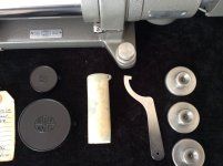
(Off-topic questions for people here: What's the white stuff visible on both springs above? Should I clean it off? How? What -- if anything -- should I use to lubricate the squeaky mechanism? I don't want to dirty or damage the optics.)

The lead screw for the slide is the central long shaft visible below. The lead screw for the indicator is driven by the small gear on the top.

IMG_8131-new.jpg

The adjusting wheel drives the crosshair lead screw through the central hole, and drives the scale indicator lead screw via the brass gear:

IMG_8129-new.jpg

There is no key or other feature to maintain the orientation of the central shaft on the adjusting wheel. So at some point in the past, the central wheel must have slipped on the shaft, but the scale indicator lead screw continued to turn, so the two of them got mis-clocked. Simple solution, loosen the screw that holds the adjusting wheel on the shaft, and spin it to move the indicator to the correct position. Then retighten the central screw that retains the adjusting wheel on the shaft.

I've also continued to work on the illuminator. I decided to build a completely self-contained illuminator into the existing lamphouse. This consists of an 0-100mA constant current source, which will be driven from an 18650 Li-ion battery that I'll locate in a hollow under the base casting.

Schematic.jpg
The circuit works as follows. The current through the LED passes through the transistor and the 1-ohm resistor to ground. So the 1 ohm resistor measures the current: 100mA of current creates 100mV on the resistor. The LM358 op-amp compares that voltage (- input) to the voltage on the voltage divider to the left. There, the 270 ohm resistor provides ~5mA of current that biases the Zener diode to 2V. The voltage divider made by the 100k and the 5k resistor give a range of 0-100mV on the central wiper of the potentiometer. If the voltage on the 1 ohm resistor (indicating current through it) is smaller than that set by the potentiometer wiper, then the opamp turns on the transistor, increasing the current flow. The circuit wastes about 5mA of bias current, but a single 18650 cell should still operate it for 20-50 hours depending upon the brightness setting.

[EDIT: it would probably be smart to add a Schottky diode in series with the battery, to protect against circuit damage caused by the user connecting the battery with the wrong polarity. There's enough voltage headroom in the circuit to accommodate a low-dropout 0.2V Zener.]

It's slightly like a ship-in-a-bottle construction. I moved the LED and holder to the lamphouse itself, so that there is no contact with the diffuser tube (they are 0.5mm larger ID)IMG_7769-new.jpg
IMG_7770-new.jpg
Here is the electronics. To set the scale, the shaft of the potentiometer is 6mm (1/4") diameter and the circuit board is about 21mm (13/16") diameter. The potentiometer for varying the intensity includes an on-off switch. The aluminum cap (threaded 3/4" x 26TPI) holds the potentiometer/switch internally, and the circuit board sits behind the LED.

IMG_8134-new.jpgIMG_8133-new.jpgIMG_8132-new.jpg

I'll drill a 4mm hole in the bottom of the lamphouse for a small power cable.

The circuit board isn't pretty , but it works correctly and fits in place, so for a 1-off I can live with it.

Cheers,
Bruce
 
Last edited:
I thought that I would update this thread with a bit more info. My AC's nice wooden storage box has two (empty) clips inside. But after browsing the web I found photos of this nice AC which was for sale a few years ago in Switzerland. You can see from the photos that one of the clips held a hook wrench (Hakenschlüssel) and the other clip held a plastic tube with a lens-cleaning cloth.

Auction2.jpgAuction1.jpg
Also missing from my box are the two lens caps. The larger of these has about a 57mm ID, and the hook wrench is for a 45mm diameter part.

The purpose of the hook wrench is documented on page 7 of this manual (page 19 of the PDF file from Dennis Dijkman, who is active here): http://vintagemachinery.org/pubs/detail.aspx?id=25444 . It allows the user to shift the eyepiece from the end of the AC to the top position, or vice versa, which answers one of my questions from an earlier post.

Also of interest is this paper: Improved performance of a refurbished photoelectric autocollimator, Milena Astrua and Marco Pisani,
Meas. Sci. Technol. 32 015010 (2021): https://doi.org/10.1088/1361-6501/abaf6f where two Italian researchers removed the eyepiece from one of these AC and fitted an CMOS image sensor camera. With software they were able to reliably measure angles of about 0.035 arcsec.

I'll post more in a week or two when a high-quality mirror arrives.

Cheers,
Bruce
 

Attachments

  • Auction3.jpg
    Auction3.jpg
    334.2 KB · Views: 4
  • Auction4.jpg
    Auction4.jpg
    319.2 KB · Views: 4
Last edited:
That's a nice unit Bruce I wish I had one in place of the early model I have myself.

I have a couple of Hilger & Watts mounted mirrors. The mirror is held in the housing by spring pressure from behind which holds it against the machined inside face of the mirror front bezel.

2mirrors.jpg

I use a cheapo LED head light as an illuminator. I just cut the headband clip off and superglued the lamp to the original lamp ring.


LED lamp1.jpg

LED lamp 2.jpg

My model does not have the option to move the eyepiece and I found it a bear to keep viewing the cross-hairs when working, so I turned up a ring and glued that to an old phone case. I use a Motorola G7 power smartphone (which has phenomenal battery life) as a viewer. I just set the camera running in video mode and it works great.

AC phonemount1 .jpg
AC phonemount2.jpg

AC phonemount3.jpg
 
Hi Peter,
I've seen some of your posts on another forum, regarding the modified headband light illuminator. That's a very good solution!
I have a couple of Hilger & Watts mounted mirrors. The mirror is held in the housing by spring pressure from behind which holds it against the machined inside face of the mirror front bezel.
One of the people here has sold me a Hilger Watts mirror sled like the smaller one in your photo, but without a mirror. He also included a lambda/10 mirror that I can mount in it. He sent me a photo of the 3-legged spring.

I'll have to slightly deepen the mirror pocket, since the new mirror is 1/2" versus the old one at 7/16". Should be an easy boring job on the Deckel. I'll post photos when I get the parts and modify them.

I assume that the front face ring has 3 pressure points opposed to the 3 legs of the spring, which the mirror rests against. Is that right?

Peter, if you come across any Hilger Watts mirrors for sale, please let me know, as I will also need a turning mirror.

Your smartphone solution is a fantastic one! By the way, what are the lines that I see in the photo? Are the one vertical and two horizontal lines done with a marker on the front face of the phone? Then the two close parallel lines are the reticule on the autocollimator, and the fuzzy vertical line to the left is the target line? Or have I totally misunderstood what I am looking at?

Cheers,
Bruce

PS: if you really want an autocollimator like mine, there was one for sale in the USA which looked functional and the price was reasonable. There's a link in an earlier post from me.
 
The two thin parallel lines with the scale alongside are on the reticule. Each line on the scale is 30 secs or one turn of the dial. The darker, better-defined crosshair lines are the cross-hair as viewed and the fuzzy cross-hair is the cross-hair reflection from the mirror. I can focus either the vertical or the horizontal reflected lines but not both together. Since I'm only using the horizontal line I have that one in the best focus in the pic.
 
BTW I have this mirror (the top left) which I hadn't thought to sell but if you have no luck finding one I will consider it. It's in fair condition, eminently useable.
Loose mirrors.jpg
 
I was getting ready to mount the power supply for my AC underneath the base. It consists of one 18650 Li-ion cell and a single-board charging circuit, that will charge it from 5V 1A or run the AC on external power.

Then I had the following thought: would heat produced by this power supply warm the base and hence distort the AC alignment? So I am wondering if mounting the battery and charge circuit under the base is a Bad Idea. Since the battery is going to provide ~ 100mA at 4.2V and its internal resistance is at most about 1/2 ohm, the total heat production would be around 10 millwatts. Is that amount of heat enough to significantly distort the AC base? Heating would be much more when charging, but presumably the system would not be charged in operation.
 
The two thin parallel lines with the scale alongside are on the reticule. Each line on the scale is 30 secs or one turn of the dial. The darker, better-defined crosshair lines are the cross-hair as viewed and the fuzzy cross-hair is the cross-hair reflection from the mirror. I can focus either the vertical or the horizontal reflected lines but not both together. Since I'm only using the horizontal line I have that one in the best focus in the pic.
A slight "potato-chipping" of an autocollimation mirror can produce the different-focus for vertical and horizontal reticle lines effect that you are seeing. The usual cause is mechanically straining the mirror in some way.

Usual suspects are overconstrained mounting, thermal distortion, or full-surface bonding with rigid adhesive.
 
I was getting ready to mount the power supply for my AC underneath the base. It consists of one 18650 Li-ion cell and a single-board charging circuit, that will charge it from 5V 1A or run the AC on external power.

Then I had the following thought: would heat produced by this power supply warm the base and hence distort the AC alignment? So I am wondering if mounting the battery and charge circuit under the base is a Bad Idea. Since the battery is going to provide ~ 100mA at 4.2V and its internal resistance is at most about 1/2 ohm, the total heat production would be around 10 millwatts. Is that amount of heat enough to significantly distort the AC base? Heating would be much more when charging, but presumably the system would not be charged in operation.

I think you’ll be fine with the battery in the base; 10mW is very low. For comparison, my phone has roughly a 12.6Watt-hour battery capacity, and if we assume a standby lifetime of 15days (generously), that is still a 35mW discharge rate, 3.5x the hearing you’re describing. My phone is never detectably warm to the touch when on standby, the AC base will not be either (I realize the convective cooling geometry is different, but they’re similar enough for rough order of magnitude estimates). Most of the heat into the autocollimator is going to come from your light source.

I admire your project by the way! Wish I had the equipment to copy you.
 
A slight "potato-chipping" of an autocollimation mirror can produce the different-focus for vertical and horizontal reticle lines effect that you are seeing. The usual cause is mechanically straining the mirror in some way.

Usual suspects are overconstrained mounting, thermal distortion, or full-surface bonding with rigid adhesive.

Thank you John.
I have two certified mounted mirrors so that is not the cause. An optics expert (retired Leica r&d tech) has identified the problem to me within the auticollimator itself. It works and I'm not ready to mess with the lenses in an effort to make it worse.
Pete.
 
An optics expert (retired Leica r&d tech) has identified the problem to me within the auticollimator itself. It works and I'm not ready to mess with the lenses in an effort to make it worse.

I have been thinking about this. If all of the optical axes are coaxial and the eyepiece graticule and target graticule are perpendicular to those axes, then there are only three distances that are critical:
a) objective to beam splitter
b) beam splitter to eyepiece graticule
c) beam splitter to target graticule
In fact I think that (a) does not matter, provided that it is close to correct, and that only (b) and (c) might need to be adjusted.

If anyone here has done this adjustments, or has a manual that steps through a procedure for this, I would be interested to hear about it.


Back
Top