What's new
What's new

How to Measure and Model a Curved Gear Rack

I was unaware you have access to proper resources.
I foolishly got the notion you were a hobby guy playing in his basement.
No offense taken or apologies necessary. I happen to work for a product development company that has a captive shop, and my boss has decided that we should be able to make just about literally anything, so I have a LOT of equipment and machinery that most don't. You gave me a lot of good info for various ways to go about this, so that's valuable in and of itself!

I'm entirely self taught, so I appreciate when people give me a lot of information. Doesn't offend me in the slightest. I posted here so I could learn.

IIRC, there are a couple freeware gear profile programs that you may be able to use to calculate the pitch diameter with.
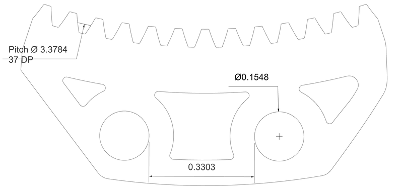
I'll look around and see if I can find any. I know my boss has one he uses when he's designing for client work, so I can probably use that. Still need baseline measurements to plug in.
What you are dealing with IS a bent rack, but is otherwise also known, as a sector of an Inside Tooth Gear.
Good to know. Didn't really know what to call this and that apparently set a few people off 😆
Another option, if you are in or near a place that has an RC car related hobby shop, is to take your parts there, and see if they mesh up with any of the standard DP gears they stock.
That's a good idea... I'll look around for a shop. There used to be a couple around here, but afaik they died a while back.
 
How badly am I off with these dimensions? How many teeth are on the pinion?

173326434.png
 
Hi trevj:
You wrote:
"What you are dealing with IS a bent rack"
While I understand what you're saying, I have to disagree in principle with the notion that an internal gear segment is equivalent to a rack but just bent into a curve.
The definition of an involute rack, is that the flanks of the teeth are straight, and this is true only of a rack...both external and internal gears have an involute profile on the teeth but the internal teeth are "inverse" to the external ones so the flank of an internal gear tooth is roughly concave where the flank of an external gear tooth is roughly convex.
There are many additional details, way too complicated for my brain to process (I'm not a gearhead by profession) but this definition is essential to involute gearing.

So although it is attractive to think of the ring gear segment shown as kind of a "rack" there are differences.

Cheers

Marcus
www.implant-mechanix.com
www.vancouverwireedm.com
 
What you are dealing with IS a bent rack,

Nope nopety nope nope, ain't no such thing. When dealing with teeth a rack is a specific thing, if it an't straight it ain't a rack. The only "bent" one that fits the definition is if you drive into a parking meter and do severe damage to the front of your car.

Or possibly when describing a lady with uneven breasts you could say she has a "bent rack" but otherwise sorry, to fit the definition of "rack" it has to be straight.
 
IMHO you need to get to the device to measure things up That is the only way to get the proper toothcount and centre to centre distance Pressure angle is a thing you could gues best on a mating gear in good shape
Peter
 
Internal gear teeth are bulbs, bent rack would still maintain a straight tooth.
It never was a zero backlash perfect meshed device. It is designed to be screwed into to a mdf box that is exposed to ice, Coke’s, diet cokes, and suicide soda concoctions. It has to be sloppy enough to get the bubble gum film just the right thickness.

Cool job btw.
 
Changing the sketch by scaling it up, as per Garwood's observation, made the diametral pitch of the sector close to 9 DP. From there, I changed the scale to make the teeth 9 DP exactly. My wild * guess is that it would have 125 teeth if un-sectored.
The mounting holes appear to use 2 of a 26-hole bolt circle.

173332807.png

I wish it were a straight-down view. And is that an 11-wide paper towel or a post-it note?
173332809.png
 
Last edited:
Nope nopety nope nope, ain't no such thing. When dealing with teeth a rack is a specific thing, if it an't straight it ain't a rack. The only "bent" one that fits the definition is if you drive into a parking meter and do severe damage to the front of your car.

Or possibly when describing a lady with uneven breasts you could say she has a "bent rack" but otherwise sorry, to fit the definition of "rack" it has to be straight.
Hi trevj:
You wrote:
"What you are dealing with IS a bent rack"
While I understand what you're saying, I have to disagree in principle with the notion that an internal gear segment is equivalent to a rack but just bent into a curve.
The definition of an involute rack, is that the flanks of the teeth are straight, and this is true only of a rack...both external and internal gears have an involute profile on the teeth but the internal teeth are "inverse" to the external ones so the flank of an internal gear tooth is roughly concave where the flank of an external gear tooth is roughly convex.
There are many additional details, way too complicated for my brain to process (I'm not a gearhead by profession) but this definition is essential to involute gearing.

So although it is attractive to think of the ring gear segment shown as kind of a "rack" there are differences.

Cheers

Marcus
www.implant-mechanix.com
www.vancouverwireedm.com

Ayup. I misspoke, and failed to get in to the details of tooth shape and form. My bad. And I know better.

And, if the estimates are that the parts are 9DP, hobby shop gears are not going to mesh... A little outside the normal range of available sizes! I thought it was a smaller part.


A good photo with a scale in it for reference would be nice!


Does the shop have an optical comparator? Even some measurements with a caliper across from one point to the same point on another tooth, or several teeth over, would go a long ways.
Should be able to find a free download for printing some polar coordinate graph paper, and that would make it pretty simple to get a decent idea of the radius involved.
 
Hi David M:
I think you were closer to the mark when you had it figured for 32 DP.
I say so because the OP is claiming the bigger part is about an inch long overall.
Your 9 DP version shows the holes as 5/8" diameter....that cannot be correct.
But your 32 DP version looked pretty good to me.

If our OP is willing to pick off some easy dimensions for us, we can probably get pretty close.
I'd want to know the chord height of the inner rib...that would establish the diameter of the rib and get pretty close with the DP of the gear.

Cheers

Marcus
www.implant-mechanix.com
www.vancouverwireedm.com
 
Three approaches I would suggest.First is to cast the new parts. You can make your mold from the old parts, because they have some good teeth. You use the old part as a mold to make your mold. Make several, and cut out the bad teeth an dsplice in good sections from the good section of one of your extra molds..
You could use epoxy both for the mold and for the finished part. You could try adding chopped glass, fumed silica or other filler to improve strength and wear resistance of the parts.
You could cast parts in wax and trhen lost-wax cast parts in metal. They will be a little smaller because of shrinkage of both the wax and the metal, but probably not enough to matter in your application.
A different aproach that would give you two parts quicker, if two is all you ever need, is to use the same segment-matching approach to trace a restored version of your old part on a blank, material of your choice, and cut it out with a fret saw, jig-saw, bandsaw, and finish with files.
 
How badly am I off with these dimensions? How many teeth are on the pinion?
Sorry. Haven't checked this in a few days. Here's what I came up with after having it on a flatbed scanner and getting some physical measurements. 13 teeth in the larger section. I'll theoretically get my hands on the mating pinion tonight to pull measurements off that.


Large Gear Screenshot.png


Internal gear teeth are bulbs, bent rack would still maintain a straight tooth.
It never was a zero backlash perfect meshed device. It is designed to be screwed into to a mdf box that is exposed to ice, Coke’s, diet cokes, and suicide soda concoctions. It has to be sloppy enough to get the bubble gum film just the right thickness.
I'm going to do my best to replicate the "perfect form" but I'm absolutely aware that there's no way I get this closer than +/-.005 or .010.
Ideally I'll be making this a complete conversion kit that I can market to other people who have the same kind of issue. If that happens, I'll just design the pinion and ring sections to match each other properly and call it good.
Cool job btw.
Right? I'm actually really excited to try and help preserve some historical stuff.
Does the shop have an optical comparator? Even some measurements with a caliper across from one point to the same point on another tooth, or several teeth over, would go a long ways.
We had an optical comparator before we moved. It was from the 30s and was annoying to move so we left it behind. I grabbed a scan with our flatbed scanner and scaled to match physical measurements. Should be close enough for the prototype I printed, but I'm still after proper reverse engineering advise so I can model a proper gear.
 
Having a couple of sizes to go by, I now believe the gear could be a 37 DP.
I pinned the fixture hole diameters at 0.160, so I'm pretty sure I'm right on that one. I measured the location of the holes multiple ways, as well, so I'm pretty sure on the distance between them. I'm assuming that the injection molded plastic is off a bit, though. Seems to be an 85 degree sector of the gear, as well. Based on that, I'd expect ~52 teeth on the whole ring?

One of the difficulties I'm having is that even the teeth that are still intact seem to be somewhat warped, so the pressure angle of 20 degrees that I see line up on some teeth is too narrow on others. I'm fairly certain it's 20 degrees, though, since that's the standard for non-metallic gears that I see all over the place.
 
Its probably .75 mod or ~38dp

You can make a replacement with laser cut plastic.

Btw, not making this up, i had a friend laser out a 4:1 planetary gear reduction from some random 3/8 thick acrylic i found on the side of the road. It actually held up to half a hp at 800 rpm, 200rpm output taken from the planet gears . I forget the exact value but the ring gear was cut to fit the 56C frame motor outside diameter, and it was bolted directly to the motor. The planets were the same tooth count as the sun gear, about 16 teeth. 12 dp range.
I expected the plastic teeth (acrylic !!) To crack under the load and stress risers... Which was a 23" diameter propeller, the motor and gears lubricated with salt water... But they held up fine.
 
Last edited:
I started using the flatbed scan instead of working from a photo.
Things came out differently.
173343795.png


I now get a diametral pitch of 34 (or .75 Mod. The radius from the gear centerline to the centers of the two mounting holes is 48mm.)
There are 106 teeth in a complete gear.
The scan, I believe, is noticeably more accurate. However, including x and y known-length references with the part would have been nice.

It will be interesting hearing about the pinion measurements and the possibility of an addendum modification. The likelihood will be low if the pinion is steel with the plastic sector.

173345999.png
 
Last edited:
Even if you are off by 1dp (shrinkage from a direct casting of the original part in aluminum) the customer probably would not notice.

But now that you have asked the gear perfection Gods, they will notice. And now you have to profile shift the plastic .75 mod gear to account for the wear on the metal pinion. And you also have to adjust the geometry of the plastic gear to account for the difference in stiffness between the plastic and metal so as to achieve zero torque ripple.
 
Last edited:


Back
Top