Wow, lots of great replies, thank you. I wasn't expecting that :-)
Can't you manually pick up the contactor for the hydraulic pump without activating the spindle motor ? That'd give you pressure without the spindle turning.
The pump is actually a spiral groove cut into the shaft. It pumps as it spins... But as another poster said the dynamic behaviour will be different. There are various effects at speed like the oil wedge etc.
The simple way to deal with this (at least what I have done with my surface grinder spindle) is set the clearance with the machine off (push up and let it settle, pull down let return etc and aim for a bit more than your target (say 7 microns) as no matter how you go about it the measurement is going to be approximate. Then you run the machine until it is good and warm and make sure it doesn't lock up. You can then tighten it slightly if necessary but with an abundance of caution.
Luke
That is exactly what I did :-) I still would like to make a good measurement. So I know I've done the reconditioning correctly, but today I did just that. Then I found a scientific article where they were estimating an oil film thickness by measuring the lift of the spindle shaft as it is turned on and reaches it's speed. I ended up using this method as my clearance got below 20 microns because by pulling on the shaft I couldn't tell how much is clearance and how much it is flexing... The lift was very obvious.
Also in that article they gave all the details of their spindle. It happened to be very similar in many ways to what I have (except the size). So after scaling to my spindle size and getting the desired oil film thickness of ~7 microns I came to a conclusion the machine manual where it tells you yo get the runout to "under 10 microns" they don't actually mean the runout... They mean the clearance. There is actually wording to the effect of "measure on the taper while slowly turning the spindle by hand". I assumed it was just a standard acceptance form used for all sorts of machines (yes, machine acceptance criteria like spindle runout was standardised in Poland long time ago). But now I believe it is actually correct.
Please tell us the brand of the machine and if you have a drawing of the spindle please attach a copy here. I would assume from what you wrote the measurement is the the push and pull of the spindle to get the.0004" movement (in and out, not TIR of the taper) of the spindle to get the correct TIR. On a grinder spindle I would hope it to be .0001" or less when the spindle is warm and rotating it by hand after it is adjusted when warm and measuring the taper. I would also buy or use a infra-red thermometer .and measure the temp of the spindle front taper at 40 C or 104F. I see your in Poland so I am assuming the machine manual is written in Polish, but the blueprint or drawing is like looking at a Playboy magazine. Who reads the articles...LOL
Sure I will.
First let me say I do have an infrared thermometer (actually two, one is a special high temperature model reserved for heat treatment) and I 100% agree with work like this it is absolutely necessary.
The brand is Jotes Spc20a, the spindle is made by a Polish bearing manufacturer FŁT (also known as PBF). BTW, it is a machine made very long time ago.
Here is a spindle drawing:

The zigzag shape on the shaft is the pumping part. It is supposed to use angular contact bearings 7206 class 5 in the back. It runs in Mobil Velocite 6.
Who makes the spindle? Model?
Different manufacturers design hydro spindles in different ways. Okuma, Cincinnati, Shiguya, B&S, Studer, Kellenberger, etc etc etc, all have different ways to skin the cat, and therefore different clearances required.
Without knowing exactly what you are working with its hard to assist much.
I do give the details above, but they are really just a curiosity. I'm almost certain people that know
anything about this specific spindle will not say a word here, because any published information affects their ability to charge pretty penny for rebuild services. One of the reasons why I started this rebuild myself is to put more information about this spindle on the net. It is an old model. Many people consider it's "plain" front bearing inferior and there is a market here in Poland for a rolling bearing replacement service for this one and similar spindles.
Your runout, if accurate, is high. This is usually either bad actual runout on the shaft where you are measuring or improper clearances allowing excess play. IMO its probably a combination of both in this case but thats just a guess. I do think your clearance is a little high on a shaft that size but again without more data we are all just guessing.
Based on grinding tests I done I think the actual dynamic runout is a lot less. Possibly below 5 microns judging by the surface finish left by a single pass with fast table speed (so one rotation is a couple of mm on the part). But I don't have a good way to measure it. Also, this is an old and worn machine with other issues that are beyond the scope of this post.
What would be a "good" runout for a spindle of this size? (note the machine is 60+ years old, but let's disregard it for now).
Dynamic runout can be measured, but doesn't necessarily mean much in this application as you could be too loose and yet only see some of the runout as the shaft is just sitting in the bottom of the saddle spinning.
Do you mean it is not loaded? As in not grinding at the moment? Yes, in some way measuring runout like this is futile and the real test is grinding... I might just have realised that now.
I've only messed with one such thing years ago. The final adjustments were done by temperature rise after running for a while.
That is how I did it today. When I got an operating temperature of 33C (same when not doing anything and doing light grinding after an hour). I decided (based on the surface finish) I don't need to push it further.
I have an interest to find out how good it can get, but I worry pushing it harder can result in very rapid damage. I've dealt with oil lubricated plain bearings before (with gravity fed oil, no pumping) and I have experienced a thermal runaway of such bearing. There isn't enough time to stop it before damage occurs when it starts unless one happens to notice the signs beforehand in temperature measurements (as one should - that thermal runaway was entirely my fault, it was many years ago and I didn't really know what I was doing back then, also the machine back then was bought for scrap value essentially).
A properly designed hydrodynamic bearing has zero run out while running at constant speed, constant load, and constant temperature.
This scientific article authors would disagree with this statement : "Experimental study of a precision, hydrodynamic wheel spindle for submicron cylindrical grinding" by J. F. Tu, M. Corless, M. J. Gehrich, and A. J. Shih". PDF attached.
The exception is a poorly designed bearing which can have a oil film wedge that rotates around the journal. The process is called oil film whirl and it can occur when the spindle is operating at high speeds and low loads.
Yes, oil whirl is a very important issue. One interesting fact I learned during research for this task is that hydrodynamic bearing bushings are designed to not be round! Having it really nice round and circular exacerbates oil whirl. The bushing should at least be crushed (elliptical) or have other geometry. And here I thought it is a fault of my spindle that my bushing is far from circular. I can describe it's shape only as triangular, or star-like with 3 inward lobes and 3 outward lobes.
The main concern when adjusting the radial clearance is bearing stiffness. The center of rotation of the journal moves with changing load. The ability of the grinder to control part size will be determined by how much the center moves when going from maximum wheel loading to zero wheel loading at spark out. A unbalanced grinding wheel will add a once per revolution error which will affect surface finish rather than part size.
One thing I woukd like to add that this in this grinder due to how it is used (finish passes taking material to final size "gently"). Spindle stiffness affects less final dimensions of the parts - once one learns how to use the machine properly. But what it does affect is surface quality at a given non-trivial grinding load. For example, how good the surface is after a single pass, 1 thou DOC, 470 ipm table feed, a quarter inch step over with medium dress?
A inductive sensor would work for measuring journal run out while grinding and would be one way to set bearing clearance based on the effective radial stiffness of the journal bearing.
The sensor would need access to the steel wheel adapter flange.
It might require a air blast to keep the sensor face clear of coolant or grinding dust.
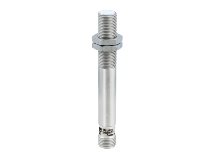
This one has a resolution of .06 microns at 520 hz. with a accuracy of 1.0 micron
High precision analog sensors

www.baumer.com
Thank you. This is interesting.