What's new
What's new

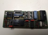
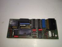
Inductive linear scale

this is video how it works now
The video was very helpful. Clearly, the upper part of the scale has a problem.
the rest of the bits fed to the display are counting correctly
Maybe, but not clear to me. You would need to turn the handcrank very slowly to demonstrate that the lower part is working properly.

As for the LM387, you can buy it on ebay, from china, or from the US, but I don't know about the logistics of buying chips where you are. It should not be hard to find a new replacement, although with the wrong pinout. I am sure you have considered making a "frankenstein chip", where a chip with the wrong pinout is soldered into a socket using very short wires to reconfigure the pinout. There are chip selectors at US websites such as Mouser or Digikey that should give you alternatives. By "internal biasing", are you referring to using a single power supply and ground? Any single-supply op-amp that has the bandwidth and noise should serve. A quick look at Mouser came up with an MC33078 as a possible option, but I spent all of 2 minutes looking.
 
New components placed, will see on thursday will this work.
As for the LM387, you can buy it on ebay, from china, or from the US, but I don't know about the logistics of buying chips where you are. It should not be hard to find a new replacement, although with the wrong pinout. I am sure you have considered making a "frankenstein chip", where a chip with the wrong pinout is soldered into a socket using very short wires to reconfigure the pinout.

Something like piggyback. Not enough space for that, as scale cover comes over this electronic, I had to back old electrolytic capacitors, because I couldn't find axial, old are OK, tested with caps meter, and esr meter. I made order for LM387, will wait for receiving, but maybe problem was not with it...will see...
 

Attachments

  • IMG_20230313_180719.jpg
    IMG_20230313_180719.jpg
    1 MB · Views: 4
  • IMG_20230315_092333.jpg
    IMG_20230315_092333.jpg
    911.8 KB · Views: 4
I tried board with replaced components, but no progress... I took scope and recorded signals...

Here are signals from MUXs control inputs ABC (I donnt know exact order, but compared to good scale this is OK)

IMG_20230317_193548.jpg

IMG_20230317_193559.jpg

IMG_20230317_193605.jpg

Enable signals on MUX1 and MUX2, they are inverted...

IMG_20230317_193731.jpg

IMG_20230317_193742.jpg

This signals are the same as with good scale, so I assume MUX are OK (I put new)....

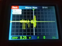
Problem is somewhere with sensed signal processing... This is output from LM387 (bad scale)

IMG_20230317_194336.jpg

This is output from LF356
IMG_20230317_194308.jpg

As it is seen, LF356 works well, it inverts input signal, and amplifies 2 times... Just what can be seen on schematics...problem is with signal shape...

this is signal from good scale (LM387 output)

IMG_20230317_193641.jpg

First part of signal is with much lower amplitude... and shape is different... so something seems to be wrong in part with LM387... I must replace all capacitors, maybe they seems to be good, but their impedance in some frequency range can be bad... I lifted bypass capacitors, and they where with 80nF capacitance (should be 100nF), so something was wrong with them... but currently here don't have all new capacitors...Maybe LM387 is problem and doesn't filtrate first part of signal...it should realize Band Pass filter (its second section).

Unfortunately I can not see signal right after MUXs, it is to small, this scope has 50mV smallest division...

Once again when on this scale I put board from good scale it works well... so sensing coils (caps) are good...
 

Attachments

  • IMG_20230317_194336.jpg
    IMG_20230317_194336.jpg
    847.8 KB · Views: 3
Last edited:
There are 2 electrolytic capacitors (4.7uF) in the filter chain. Did you actually replace them with new caps, or did you just test them and put the same ones back in? The reason I ask is that I can see the exponential decay of your ac coupling on your "bad" signal, but not on the "good" signal. I would particularly want to replace the 4.7uF in series between the two amplifiers.
 
Finally I found what the problem was. I was thinking, thinking... when you hit the wall, you sit and think...There was no problem with any component... Problem was PCB... and dirtiness.. over years thin conductive film was formed around pads.... I cleaned every pad with an awl (I circled around them)...dirtiness formed parasitic resistors and capacitors and they affected small signals from sensing elements...

This scale was the most exposed to emulsion and other dirt although its slot is oriented downward.

This is how it works now...


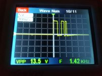
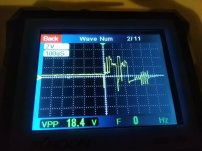
And here are signals from LM387 and LF356...

IMG_20230318_123409.jpg

IMG_20230318_123428.jpg


Back
Top