What's new
What's new

integrex alignment

I shouldn't dignify an answer to that question, but yes, and I know Phil does and TomB, don't be a dick newb. If you can find me a better applicable indicator than a Blake send me a link I will buy it tonight.

Robert

Blake indicators are terrible in a horizontal application like that. Maybe in a vertical application where tenths don't matter like it will in his situation. He need to get the alignment as close as possible between milling spindle and turning spindle or else he's alway off between x-y mode and x-c mode machining. Can't just "shift" x-c machining, it is what it is on these.
 
Like I said dude, show me a better/more applicable indicator and I will get it TODAY! My thought is that a Blake® and Haimer® 3D Taster working together is the way to go, but if you got a better idea by all means. How on earth you're coming up with the Blake being no good horizontally is mind blowing since the body of the indicator doesn't move.? But since you haven't I'll go ahead, STFU.

Robert my ±2
 
call me old fashioned but a regular test indicator works just fine for alignment even if i have to use a mirror to see the dial
.
the other test is a 0.5000 pin in a hand tightened tool holder with confirmed low runout should line up to a just bored (not drilled) 0.501 hole in a part in a headstock chuck
.
i handle mode around to put pin in hole. if not aligned the hand tightened pin slides into tool holder. rude and crude but get me within .001" every time and does not cost much.
.
if i got a machine way off i would not be waiting days for a expensive special indicator to be delivered. i could use any test indicator or even a 0.5000 gage pin and measure alignment in less than 2 minutes
 
call me old fashioned but a regular test indicator works just fine for alignment even if i have to use a mirror to see the dial
.

On a vertical, yes. On a horizontal, no.

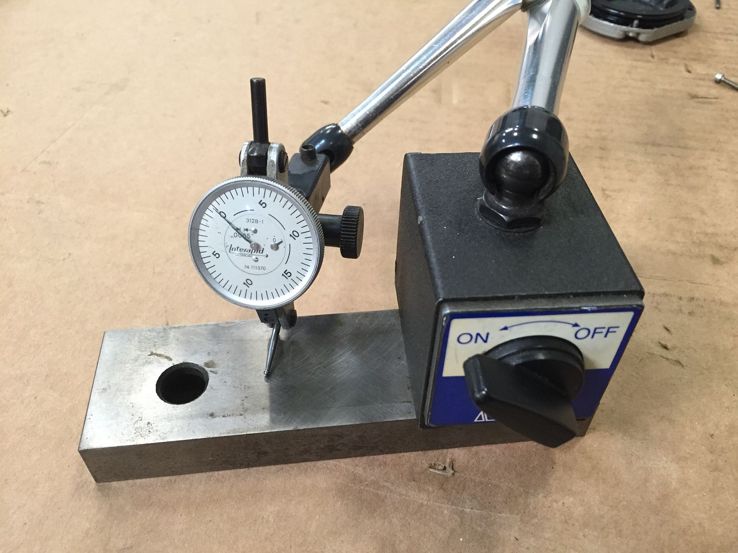
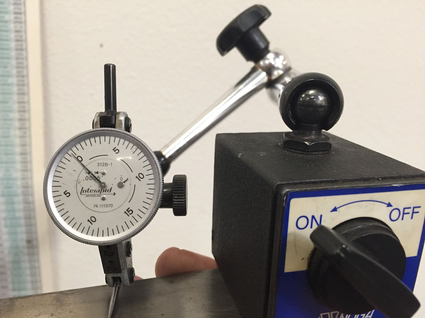
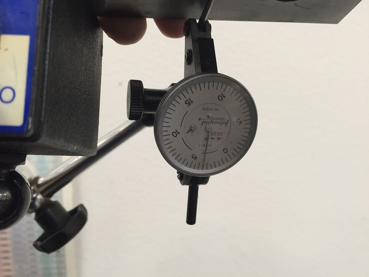
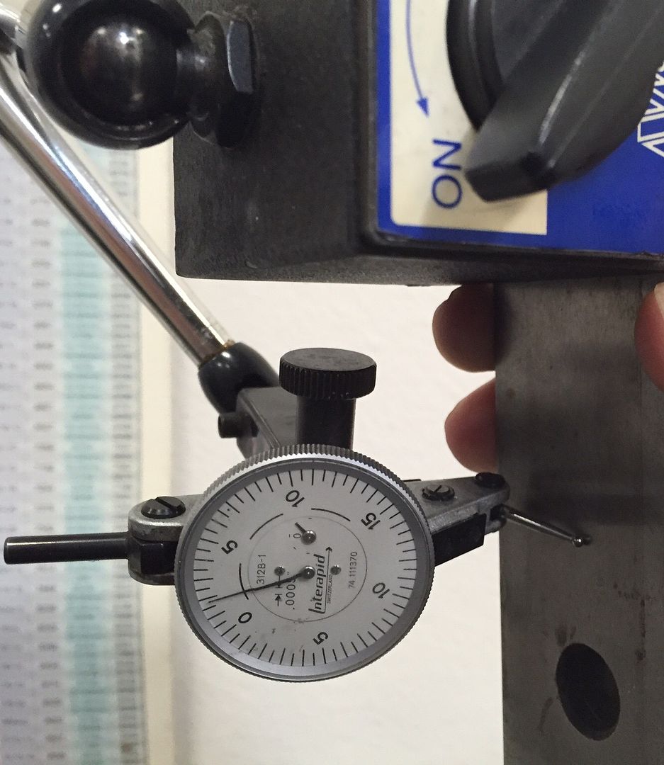
Try this little experiment with your most trustworthy indicator.

19A7CA60-174D-47E9-A2CB-FE3C866F7A68_zpsydwto2v1.jpg


179E34EF-7AB8-4647-8C88-7F60C33EFC37_zpsioimse29.jpg


F1BEF056-2E12-45D5-854E-F2C77AD30A4C_zpsmur2usjv.jpg


0BEFEB87-954A-41D0-A920-DCEB0B8DB5E1_zpszap4dotn.jpg
 
you put just the test indicator and nothing else in a tool holder and it will not sag more than .001.
.
they are specifically made not to sag more than that.
.
if you hang a indicator off of 12" of magnetic base rods of course those rods will sag. i was taught to clamp on to a piece of pipe the indicator and rods and clamps if i wanted a long setup, then zero indicator and turn pipe 180 and measure the sag and use that compensation number for that particular length setup of rods, clamps, indicator.
.
this is required if indicating a electric motor to a pump that is connected with a coupling you have to span the gap.
.
checking a mazak there is no reason not to just use the indicator reading a freshly bored hole of a convenient size say 0.300 to 0.500 so you need no rods clamps or anything else just the indicator alone.
.
feel free to spend $1000's of dollars for nothing. there are many machinist who have figured out how to do it for less. thats why the test indicator shown has a round rod on the end to go directly in a collet holder
 
Joe I appreciate your link, but $600.00 maybe not today but tomorrow :D :D :D. But I do agree with TomB there is droop. I am not sure what the pictures you posted are supposed to tell us? 1 good indicator on a vice jaw with a good holder and you holding it at different angles, well yeah there is going to be droop. What you are showing is expected not unreal. Indicator droop is a phenomenon not something predictable. Or I should say the phenomenon is predictable but a real PITA. TomB's point I think, is that a gage pin is going to give you applicable results, not numbers or values, and fast.

But that just my ±2 Robert
.
indicator AND rods AND clamps total sag can be setup on a big rigid pipe with same angles lengths etc and sag measured and compensated for on up and down readings
.
the other thing taught is heat rise alignment. a lathe headstock will rise or grow as it get hotter. the end by the lathe chuck might be a different temperature than the other outboard end. thus the lathe spindle can tilt out of level as it warms up.
.
any ideal alignment or grid shift should be done at running temperature. i used to indicate the coupling alignment between a turbine and motor when it was hot and just shut off. i would take indicator readings every 5 minutes and see the readings change as things cooled off. you can put a magnetic wood stove thermometer on each end of lathe head stock and try to calculate heat rise. but my experience is run it and get it up to running temp shut off and take readings within a few minutes.
.
i see every day coolant can also have a big effect. cold coolant can be as bad as hot coolant. i use a temperature controlled 2000 gallon coolant system with refrigeration system to control the coolant temp
.
by the way when i measure grid shift, i can and often have taken 3 readings about 2 minutes apart and can see the readings drift to normal running alignment numbers as the machine warms up. grid shift definitely changes as machine temperature changes. i see this every day. many cnc machines have a internal cooling system trying to maintain a constant temperature. many cnc machines sense temperature at different parts of the cnc and compensate the digital readout as temperature changes
 
Like I said dude, show me a better/more applicable indicator and I will get it TODAY! My thought is that a Blake® and Haimer® 3D Taster working together is the way to go, but if you got a better idea by all means. How on earth you're coming up with the Blake being no good horizontally is mind blowing since the body of the indicator doesn't move.? But since you haven't I'll go ahead, STFU.

Robert my ±2

Wow, long on bluster aren't you? Are you just trying to pad your post count? A Blake is ok if you're trying to get within .005" or so in a horizontal application. Ever seen a Blake co-ax graduated in tenths? There's a reason why!! Look at all the moving parts on one of those. I'll take a tenths indicator on a short stem, thank you.

He needs to get those spindles adjusted within .0003" or better.

Note my method of checking runout involves no movement of the indicator, it's held stationary and part is revolved around it. No droop.

Rob, follow your own advice:

STFU.

Robert my ±2
 
Indicators, lasers, and all others such things for sure help get in the ballpark.
But there is a point in 5,6,7,8 axis machining where you need you test cuts that load the machine and show you what and where to tweak
Devising such a test depends on your machine and where you mostly work from the centers and is for sure not easy.
One of my guys did his fifth year thesis on this and while a crazy bright straight "A" engineer he was not able to really solve it and it drove him crazy.
(I led him into it knowing, it's not a solvable problem and upcoming engineering star "rocket scientist" need these real world problems. I did give him a very high rating)

It will never be right everywhere. Life just sucks as soon as your machine movements are not straight lines but instead axes of rotation in space.
Even what should be simple backlash comp on a 3 axis is different when cutting than nice slow and easy checks.
Servos lag, slides stick or overshoot, ballscrews compress and stretch. Pitch, Yaw and roll happen at speed but not when moving slow.
No rotary axis is perfectly straight to the world of the machine yet the computer expects it to be.
I always liked the old circle, square diamond test as it actually cut something and was run at a normal machining speed.
Ancient test to many, yet real world not something that ignores the fact that a machine tools bends, deflects, twists and moans when making a part. .
People think a .0001 servo will follow .0001. It does not work that way. It will stop on your indicator within one tenth no problem, easy peasy.
Your indicator will always say zero when stopped. You can not read it while moving. Stopped is not cutting parts.
A one tenth increment cnc can not make two-three tenth round holes. It just can not interpolate this no matter how much money you spend.

Some of my customers have 2 to 5 million dollar machines that are just crazy good.
Yet they still need the very important guy that knows, when doing this or that, you have to tweak a bit this way, a little that way.
Someday, perhaps the machines and CAD/CAM computers will agree. CAM systems could maybe "get" rotaries off a few tenths or not quite right rotations about center.
Till then you tweak in features and maybe that's not so bad as it keeps skilled people in the loop.
Every year brings us closer and if you have been around to compare 1970's to now, we have gone a long way towards this goal..

Alignment info from people who own this machine would be best for the OP.
I don't know shit for advice as I don't have one and mostly grinders and much simpler 5 axis mills here.
Bob
 
you put just the test indicator and nothing else in a tool holder and it will not sag more than .001.

Not all indicators are created equal. Some indicators, even if they are the same brand, will sag way more than others due to gravity. Machine up a test block to hold the indicator rigid and you will get the picture.

Thanks to Joe for the visual. :cheers:
 
indicator sag

Not all indicators are created equal. Some indicators, even if they are the same brand, will sag way more than others due to gravity. Machine up a test block to hold the indicator rigid and you will get the picture.

Thanks to Joe for the visual. :cheers:
.
the test indicator shown can be directly mounted in a tool holder and sag will be less than .001 and usually it will be far less than that
.
people who insist on attaching 12" of indicator rods and clamps to extend it when it is not needed should not complain about indicator and rod and clamp sag.
.
why dont you just attach the indicator to 3 feet of rods and clamps and indicator. buying a special indicator in not needed. the sag problem is not from the indicator but 95% from the rods and clamps extended out. you attach indicator as short as possible <1" to a piece of pipe and zero and rotate and you will see less than .001". only time i have seen higher is when test indicator needed repair
 
Sorry, in the middle of a run.

I understand the effects of gravity on indicators. Had to demonstrate it to our maintenance crew.
indicating was done using the same setup we use on our horizontal jig bores.

It is looking like it may be a B axis alignment issue.... I am planning on running some x-y vs. C axis cuts near the end of next week. I am not convinced yet. I do believe the machine repeats, I don't believe it is an encoder type issue. I would think that would show up in any positioning / repeatability moves and I am just not seeing it.


Back
Top