What's new
What's new

Intermittent Drum Switch Operation

IMG_8339.jpg

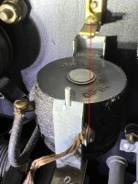
DC Control Panel (on the right). The terminals are at the bottom. Terminal labels are above each terminal. Wires have metal tags that identify them.

Cal
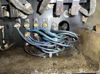
 
The drum switch has wires with metal tag numbers, 1, 2 and 3.

Red one, #1 & #2
Black ones #1, #2 and #3.

View attachment 343903
Those are not the correct wire numbers. The red wires go to the Start/Stop station and prevent the MG from starting unless the switch is in the center (spindle stopped) position.

The black wire that connects to the center terminal and has the jumper that goes to the center terminal on other side is C3. The two wires that connect to the terminals nearest the shaft are C1 and C2. The one on the terminal facing the camera should be C1.

Cal
 
DC Control Panel (on the right). The terminals are at the bottom. Terminal labels are above each terminal. Wires have metal tags that identify them.

Cal

Yup, got there. I see a corrosion problem on the three things in the upper right corner. I've found the labelled terminals at the bottom and will go after chasing down as you have described.


I'll spend more time with the numbering at the drum switch to be sure I have it clear.

Thanks. May be a bit before I'm back.

Rick

Monarch 10EE DC Panel 1 03-08-22 640.jpg Monarch 10EE DC Panel 2 03-08-22 640.jpg Monarch 10EE DC Panel 3 03-08-22 640.jpg
 
When troubleshooting these types of problems a simple continuity check is first.

However, sometimes the dirty connection is resistive meaning it looks good with ohmeter but not good with load.

Further testing requires measurements to be made live, under power.

Example is place voltmeter across any switch.

When "OFF" you read whatever the open circuit voltage is.

When "ON" is should ALWAYS read ZERO.

Sent from my SM-G781V using Tapatalk
 
Pulled the C1, C2 and C3 wires from the DC Panel and labelled them. Did a continuity check from each labelled DC panel wire to the drum switch. Labelled the drum switch wires accordingly. Reassembled switch into headstock and powered it up. Same behavior. First time rotating the drum switch, spindle turns immediately. Subsequent rotations of the switch, does not run/turn. Previously, it would run again fairly quickly but recently, it doesn't run at all, even if wiggled or left in that position. It has on occasion started after being left in the Forward position for a little. I don't like doing that so I have never left it that way long or diverted by attention.

This tells me the drum switch is not likely the problem. Where do I look/go now? Do a powered up voltage check as Tony describes?

Thanks,

Rick

DC panel wires
DC Panel Wires to Drum Switch 03-08-22 640.jpg

Cleaned drum switch contacts
Drum Switch Cleaned Contacts 03-08-22 640.jpg

C1 Continuity positive
C1 Continuity Check DC Panel to Drum Switch 6 03-08-22 640.jpg

C2 Continuity positive
C2 Continuity Check DC Panel to Drum Switch 03-08-22 640.jpg

C3 Continuity positive
C3 Continuity Check DC Panel to Drum Switch 03-08-22 640.jpg
 
First step of troubleshooting is thou shall check voltages so yea, voltage measurements are gonna be in your future if the switch and wiring is indeed not the issue.

I'm going out on a limb here but what happens if you move the drum switch slightly while checking continuity. Idea being the switch may be prevented (dirt/wear) from switching all the way when installed. Not hard to check so you could check that off the list.

I get what Tony is saying about how to check the voltage across a switch. This means I will power up the lathe with the drum switch removed, in order to access the switch contacts. That will take some care as my only access to the drum switch is by leaning over the bed, quite close to the spindle, if I'm understanding correctly.

However, I think I do not fully understand what you are suggesting. I think I get what you mean about rotating the drum switch slightly to check continuity, but from what position? From closed where there is continuity, to see if that circuit is broken as the switch moves slightly? How would the switch be prevented from switching all the way when installed? I can tell you that the switch rotates quite easily by hand, so there would have to be some fault in the mechanical connection between the switch shaft and the actuating lever/shaft operated from the front of the machine. That is such a direct connection, it is just the slot in the shaft that receives the switch shaft/dowel pin. Do those slots get enlarged by wear? Or?

I'm grasping at things, trying to understand. I can do the slight movement continuity test, but please elaborate a bit more on what might be leading to the switch not getting rotated enough.

Thanks,

Rick

Yea, you got what I was saying with respect to the switch. I don't have a clue what would prevent the switch from making contact (dirt, slop in the lever arm, maybe nothing at all!), I'm just trying to cover all bases from 1000 miles away while you already testing the unit. A common practice when trying to figure the root cause of electro-mechanical issues is to move stuff around in an attempt to locate something strange going on. Loose contact that only shows up when it is moved a certain way, solder joints that look good but aren't when placed under stress that kind of stuff. Simulating the movement of the lever may introduce the same error that is causing the problem.

Your issue may not have anything to do with the switch I was just wanting to go over the part with a fine toothed comb in the off chance there is something mechanically wrong.
 
And just as an aside, Cal is hands down the guru with this drive system. He has countless posts over the years on here helping people get things diagnosed. I will spend a bit of time looking over his previous posts in an attempt to find other scenarios that match yours.
 
One easy test you can do is to turn off the lights and look for sparks.
Some things should spark: relays, switches, motor communitators, but
most other stuff should not spark. If you have a loose connection
you may see it.

Also look for discoloration around screw terminals. Loose terminals
generate heat and you may see the effect.
 
Pulled the C1, C2 and C3 wires from the DC Panel and labelled them. Did a continuity check from each labelled DC panel wire to the drum switch. Labelled the drum switch wires accordingly. Reassembled switch into headstock and powered it up. Same behavior. First time rotating the drum switch, spindle turns immediately. Subsequent rotations of the switch, does not run/turn. Previously, it would run again fairly quickly but recently, it doesn't run at all, even if wiggled or left in that position. It has on occasion started after being left in the Forward position for a little. I don't like doing that so I have never left it that way long or diverted by attention. ...
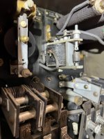
It could be a sticky AP (Anti-Plugging) relay. The AP relay is at the top of the DC panel, in the middle. It should close immediately after the spindle stops. Crud can build up on the moving arm and cause it to stick in the open position. The AP relay doesn't open until about 400 RPM (at the motor) so if you turn the speed control all the way down, you should be able to start and stop the spindle without it sticking open. Keep an eye on the AP relay when you stop the spindle at speeds above 400 RPM and see if it's sticking.

The resistors at the top-right of the panel are on their way out and need to be replaced. One of them is related to the operation of the AP relay, but won't cause the symptom that you describe. We can talk about that later.

Cal
 
Last edited:
It could be a sticky AP (Anti-Plugging) relay. The AP relay is at the top of the DC panel, in the middle. It should close immediately after the spindle stops. Crud can build up on the moving arm and cause it to stick in the open position. The AP relay doesn't open until about 400 RPM (at the motor) so if you turn the speed control all the way down, you should be able to start and stop the spindle without it sticking open. Keep an eye on the AP relay when you stop the spindle at speeds above 400 RPM and see if it's sticking.

The resistors at the top-right of the panel are on their way out and need to be replaced. Two of them are related to the operation of the AP relay, but won't cause the symptom that you describe. We can talk about that later.

Cal

I check operation of this relay, the AP Relay.
Monarch AP Relay 03-10-22 640.jpg

I actuated the first time the drum switch was rotated to forward and the spindle turned, but then subsequent drum switch rotation it did not (neither). Then I pushed the relay with a wooden dowel and tried again. I began actuating every time the drum switch was rotated, either Forward or Reverse. Then, after several actuations, it didn't. Another poke with the dowel and it worked quite a few times and was still working when I stopped trying.

It would appear we've may have found the problem. Is there something I can do to improve its operation? Clean terminals, replace the spring?

Also, I am interested in hearing about what needs to be done with those resistors. Are there direct replacements available?

Rick
 
Probably what's going on is that there's enough sticky, oily stuff accumulated between the horizontal arm and the end of the coil that the arm is sticking to the coil. (I'm talking about the relatively heavy arm with the larger spring attached to one end, not the smaller arm with the actual contacts). Get a piece lint-free cloth (old cotton T-shirts are ideal), dampen with isopropyl alcohol or electric contact cleaner, feed it between the arm and the coil, then push the arm against the coil and gently pull the cloth out. Repeat until the cloth comes out clean. There's a little shoe at the end of the arm that may also be the culprit. A little contact cleaner there might do the trick, but don't get carried away. Most hardware stores carry electric contact cleaner. Let me know how that works.

Here's a link with information about replacing the resistors: Start up problem with m/G machine?

Cal
I am having trouble with the AP relay again. I've reviewed this thread and the linked issues. I've cleaned the relay in every way I can think of. Photos inserted below. This has not fixed the problem. In the past, this did relieve the problem for a time but it seems to be worse than before in that I have to manually release the relay after just about every time turning the spindle off. I've taken to leaving the covers off as I have to lean over and jiggle the relay arm. When I do, it seems very stuck, and more so than in the past.

Above, Cal observed that my resistors need replacing, which I have not done. In one of the other threads, I think it was mentioned that one of them, the 2K ohm one?, was related to operation of the AP relay.

I am interested in thoughts and comments on how to resolve this.

Thanks,

Rick


AP Relay 1 04-20-23.JPGAP Relay 2 04-20-23.jpgAP Relay 3 04-20-23.JPG
 
If the AP relay is the problem, you can make the machine run by connecting a jumper across the terminals. The top bolt is one terminal and the bottom pair of bolts (and the frame of the relay) are the other. The machine will run just fine without the AP relay, but you should make sure that you let the spindle come to a full stop before changing directions.

The resistors will not cause problems starting the machine. If the 2000 Ohm B-E resistor is bad, the spindle will cycle on and off repeatedly above a certain speed.
Thanks, Cal.
I do not change directions much at all. I think waiting for it to come to a complete stop before reversing would not be a problem. But, it is possible to do that by accident. Just so I know the risks, what are the consequences should that happen?

Would jumping as in the photo below be what you are meaning? These locations look to be the easiest to connect to and do not involve attaching anything to the moving part. Or would it be better to remove the relay from the circuit by disconnecting the lead on the left side and extend it to the brass tab above the rely, as in the second photo?

Are there any opportunities get a replacement rely?

Rick

Jumped AP Relay 3 04-20-23.jpg Jumped Around AP Relay 3 04-20-23.jpg
 
Last edited:
Thanks, Cal.
I do not change directions much at all. I think waiting for it to come to a complete stop before reversing would not be a problem. But, it is possible to do that by accident. Just so I know the risks, what are the consequences should that happen?

Would jumping as in the photo below be what you are meaning? These locations look to be the easiest to connect to and do not involve attaching anything to the moving part. Or would it be better to remove the relay from the circuit by disconnecting the lead on the left side and extend it to the brass tab above the rely, as in the second photo?

Are there any opportunities get a replacement rely?

Rick

View attachment 394233
Reversing a DC motor while it's running, by changing the polarity of either the armature or field, is called "plug reversing". If you do it at full speed it can damage the motor. The AP (Anti-Plugging) relay prevents you from plug reversing the motor.

You can bypass the AP relay by connecting between these two terminals:
jumped-ap-relay-3-04-20-23-jpg.394233

Do not use either of the coil terminals on the side! It would be cleaner to connect to the terminals on the back of the panel.

I now see why your AP relay isn't working. The braided copper wire is not original. The original wire was tinned copper and connected to the moving contact arm via a small hole at the top of the arm:
EE38128 IMG17379c anno.JPG
The original wire appears to be soldered to the arm. Without the wire, the AP relay won't operate reliably.


Back
Top