What's new
What's new

Lapping Question

Joe Michaels

Diamond
Joined
Apr 3, 2004
Location
Shandaken, NY, USA
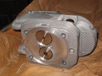
We are in the midst of repairs to our Alco S-1 diesel locomotive. This locomotive has the McIntosh & Seymour 539 diesel engine, naturally aspirated, about 12 x 13" cylinders. Each cylinder has its own head. Each head has a "spigot" or "ring tongue" which seat in a circular groove machined in the top end of each cylinder liner. Originally, the design used a ground joint between the bottom of the "tongue" on the heads and the seating land at the bottom of the circular groove.

Over time, this ground joint develops leakage. If caught in time, the fix is to install a copper "fire ring gasket". Unfortunately, this locomotive developed a head/liner joint leak last season, and while we cut out the injection pump on that cylinder, it still puffed through the leakage path for the operating season.
This spring, we pulled the head off that cylinder. There was heavy "wire drawing" (erosion due to the leakage of high pressure gasses, probably some at high temperatures when the pump on that cylinder was not cut out). The bottom of the cylinder's "tongue" looks like someone took a cutting torch to it. The bottom of the the liner groove (which I have not seen first hand) is reported to be "better", but still wire drawn.

We have been rebuilding a reconditioned head (new seats were installed prior to our getting this head), and it has a good seating surface on the tongue.

That brings up the matter of the seating/sealing surface in the liner. The copper fire ring gasket is flat annealed copper, 0.020" thick. Not much chance of it taking up much beyond very shallow leakage paths. We do not have another cylinder liner to change into the engine, so have to make the liner that is there work.

My idea is to lap in the bottom land of the circular groove in the liner. Unfortunately, the other heads are on the locomotive, so there is no way to use the reconditioned head to lap against the liner's seating surface. That set me to thinking of making a lapping tool. The first thought was to get a disc of cast iron to make the lapping tool. Of course, a disc of cast iron about 15" diameter x 2 or 3 inches thick is not easy to come by. Thinking of what was readily available, I came up with the idea of using the flywheel from a GM diesel truck engine. It is the right diameter, and should be cast iron. A buddy gave me a flywheel off a running engine (he got a new clutch kit with new flywheel). I machined an arbor with a "pilot" to fit snugly into the bore in the flywheel, and enough shank so we can get a handle on it to turn it during the lapping. We will machine a "dummy" ring tongue on the flywheel, replicating what is on the cylinder head, only a touch deeper.

Having got to this point, I am now thinking: "what do we use for lapping compound ?" Choices are to start with a coarse grit "Clover" lapping compound, or, to use "Timesaver" coarse grit for cast iron bearings. The unknowns here are:
-is the liner harder iron than the flywheel ? My thinking is the liners were often centrifugally cast from "gun iron", so am hoping the liner will be harder than the truck flywheel/lapping tool.
- how deep is the wire drawing, and will coarse lapping compound take it down to a good surface ? I've lapped in horribly wire drawn steam stop valves with 10" diameter discs using what used to be called "railroad grade" lapping compound (no longer available). The coarsest grit is either 60 grit or 40 grit now available.
-can we turn the lapping tool with a 3/4" electric drill motor for the roughing down rather than have to sit there twisting the tool up and back a few times, then advancing it a portion of a turn and starting the same repetitive cycle (as you do when grinding in engine valves) ? My fear is that using a drill motor to turn the lapping tool will result in circular scoring, so I am shying from this, but at the same time, we need to remove some material in order to get an unbroken seating surface.

I am probably over-analyzing this, but it is uncharted waters with only once chance to get things done right. Any suggestions as to lapping method (twist and turn vs drill motor), or lapping compounds to use are greatly appreciated. I know Time Saver will work to lap in a cast iron bearing with a steel journal, which is sort of what we are trying to do. On the other hand, my gut is telling me to just get a can of the coarsest "Clover" lapping compound and grind things in with that. The lap will be faced square to the arbor and flat, and we are starting with a freshly machined lap. By moving the lap around as one does when grinding in engine valves, we should be able to get a relatively flat surface, or at least flat enough that the copper gasket can do the rest. I imagine a couple of thousandths out of flat over the circumference of the joint are sealable as long as there are no wire-drawn grooves. We'll machine the lap this week, based on the measurements of the ring-tongue on the reconditioned cylinder head. Any recommendations as to surface finish on the lap ? Smooth surface finish, or a coarse facing cut to provide some spiral grooving to hold/work the lapping compound against the surface of the liner ?

Thanks !
Joe Michaels
 
Joe,
I’m not sure I have followed all your description but but some 20 or more years ago I had to sharpen a cutter that was specially made to refresh the seat for a cylinder head gasket from a Deutz air cooled tractor engine .
Best I can remember the cylinder head looked something like this one that I found in an image search
New Deutz FL913 913 Diesel Engine Cylinder Head 2239097 2230878 | eBay
I have attached an edited picture with the red line showing the surface that was too be recut by a few thou to let a copper gasket seat properly .
It could also have been to reface the end of the cylinder sleeve as well but it was a long time ago and I didn’t see what happened after I sharpened the tool .
I can’t seem to find a picture of the tool but it had flat end teeth with minimal end clearance like 1 or 2 degrees . along the lines of a shell end mill and a shank to turn it by hand .
You might say it was a combination of a shell end mill with a large bore on a body of a saw tooth or Forstner wood working drill
http://www.hanvitools.com/upload/big/HSS_Shell_End_Mill_1_14_1375691319.jpg

HSS Forstner & Saw Tooth Bits - Lee Valley Tools

I was wondering if you could cut some slots in your lap and turn it into a fly cutter to hold some H.S.S. tool bits or carbide inserts with minimal end clearance that so that you could you could cut off the worst of the surface before finish lapping .
Perhaps 3 or 4 tool bits would be enough.
With minimal protrusion and end clearance and perhaps a little negative rake in the front to prevent the cutting action from being to aggressive you might be able to turn it carefully by hand .
You could grind the tool bits square on the end with a degree or two of back clearance on a surface grinder and set them in the head with an indicator.
if you want to get fancy and maybe save a little time you might be able to fit some square hole sleeves to hold the tool bits.
Tool Bit Holders & Sleeves | MSCDirect.com

P.S. maybe you can find some coarse abrasive powder you could mix with grease from some of the folks who supply the people who are tumbling and polishing gem stones.
Regards,
Jim
 

Attachments

  • Deutz Cylinder Head.jpg
    Deutz Cylinder Head.jpg
    95.5 KB · Views: 1,381
Is there no chance of pulling the liner and getting it in a lathe to clean up the groove? You could use a big steady or work around a cat-head. You don't need a lapped finish to get a fire ring to seal. I am afraid you will be lapping until the second coming.
 
Is there no chance of pulling the liner and getting it in a lathe to clean up the groove? You could use a big steady or work around a cat-head. You don't need a lapped finish to get a fire ring to seal. I am afraid you will be lapping until the second coming.
Joe I agree here. We commonly "lap" steam valves by cutting segments of adhesize grinding discs and sticking them om a machined lapping tool about an inch apart. The gap give the chips and grit a place to go. But for >020 this is till a stretch. Pull that liner, clean up both ends and add new copper gaskets accordingly. This is a "fix". The other solutions are "make dos". The "fix" will serve you much better in the long run .I'm currently barely mobile but someday hope to make it up your way for a ride.
 
Last edited:
Last edited:
I read through twice and am not clear on how you want to HOLD this lapping disc. Do you have a fixture to hold it straight and on-center so you don't egg the cylinder?

I know you have a part to go in the cylinder just like the head, but I'm thinking that it's gonna take King Kong, or a long lever, to hold that drill motor, assuming it has the stones to turn the lapping disc.

If you set up a fixture, you can belt it to something and work it the way a cylinder boring machine works. Or you could just USE one of those, like Jim Christie suggests, and maybe lap the fit in after boring slightly short of final dimension.

maybe I don't have a good mental picture of what you want to do.
 
Thank you to all of you who've been responding to this thread.

The seating groove is about 1/2" wide x 1/4-5/16" deep. The seating land to be resurfaced is a flat "ring", approximately 13" ID x 14" OD. The "fire ring gasket" is like a thin copper "Mason Jar" type of gasket.

Egging the cylinder is not an issue, since this is a flat face surface that needs refinishing. The dead-weight of the lapping tool should furnish the downfeed.

The lapping tool is to be machined to a good close running fit in the ring-groove, so the inner and outer sidewalls of the ring groove hold the lapping tool square, aside from the dead-weight of the tool. The liner stands approximately plumb and the bottom of the ring groove is approximately level since this is an in-line engine.

The lapping disc has a "tongue" machined on it so that it mimics what the cylinder head does to mate down into the ring groove on the liner. The actual lapping area is fairly small relative to the entire diameter of the lapping tool.

The lapping tool consists of the flywheel from a GM diesel engine (one of the V-8 engines used in heavier pickups and flatbeds). The flat face of the flywheel, where the clutch contacted it, is to be machined so it replicates the male "ring tongue" on the cylinder head. The crankshaft face of the flywheel has a shaft coupled to it using the original crankshaft/flywheel bolt circle. I made the shaft or "arbor" with a "pilot" machined to a snug fit in the bore in the flywheel where the transmission pilot bearing was seated. The arbor can be driven by hand, or with the 3/4" electric drill motor.

Again, the only surface to be refinished is the flat circular land at the bottom of the ring groove in the liner. Not much surface area there, and the sidewalls of the ring groove in the end of the liner should act as a radial guide bearing for the lap. We are not lapping the sidewalls at all.

Hopefully, with these further details, the problem is a bit easier to visualize.

By way of lapping jobs, we did one years ago on the cylinder head of a steam locomotive. The original cylinder head had gotten launched off the end of the cylinder when the locomotive "took a drink of water". The slug of water had been rammed by the piston and the result had done incredible damage. A new cylinder head was made by hogging it out of a burnout of very thick steel plate (like 8" thick plate) on a vertical turret lathe. The design of the locomotive called for a ground joint between the head and cylinder flange. We were faced with lapping in a joint on a horizontal cylinder, and a head that weighed somewhere around 800 lbs.

What we did was some backwoods engineering at its finest. We made a roller steady to support the new head on the circumference of its flange using a couple of urethane tired casters lagged to a plank and adjusted for height with wood wedges. That problem solved, we then had to figure out how to apply a force along the centerline of the cylinder bore to the end of the head while allowing the head to rotate relative to the cylinder. My buddy came up with the idea of using an old clutch throwout bearing and a porta-power (hydraulic jack or ram). I forget what we bucked the porta power against, but it effectively made a lathe tailstock with a live center to push against the center of the cylinder head. The last hurdle was how to turn the cylinder head. I took a piece of 2" schedule 80 steel pipe about 8 feet long and welded two heavy bolts to it to make a spanner. The bolts fit into the bolt holes in the cylinder head.

We washed everything down with solvent from a parts washer tank, and slathered on the coarse lapping compound. We then pumped the porta power just enough to seat the cylinder head against the flange. With that, we put the spanner in place. I go 190 lbs and at the end of the 8 foot "handle" on that spanner, I could not move the cylinder head. One of my buddies, who goes an easy 220 lbs got on it with me. We got the cylinder head turning and we could hear and feel the grinding action. Getting the spanner handle back in the opposite direction initially took three of us pulling up on it. It did not take long, a few "back and forth" partial turns, and we kept dribbling on solvent from the parts washer to mix with the lapping compound. I think we made one additional application of lapping compound, and in short order, after a few back-and-forth partial turns, we felt things "break free", accompanied by the smoothest gliding feel to the spanner handle. We knew we were there. We took down the head, and after washing it with solvent, it was apparent we had perfect contact- a nice lightly "frosted" lapped finish (kind of like when you blow your breath on a cold window pane in winter).

It took a LOT of beef to first turn the cylinder head, but that was a much bigger diameter and much larger contact area than this diesel locomotive head's seating surface. We are also not using a Porta Power to push the lapping tool down, just the dead-weight of the tool itself. For this reason, I am thinking that we will try running it by hand first. If the torque does not seem too great, we'll couple on the drill motor with a "U joint" so the drill motor does not cock the lap or take the lap off seating parallel with the liner's seating surface.

In the meanwhile, I am going to hedge my bets and put the word out for another Alco 539 cylinder liner. As a commentary to the times we live in: the fellows who had the stash of Alco 539 engine parts are in East Hartford, Ct. Seemed like a good neighborhood. We picked up the spare heads, valves, guides, and gaskets from them and asked if they had any cylinder liners. They told us: they had put a set of 6 used/serviceable liners outside their shop on a pallet overnight. Some thief made off with a set of 6 cylinder liners during that night. Who would think thieves would steal cast iron cylinder liners ? If we had a good liner to pop into our engine in place of the chewed-up one, we'd be doing it. We've got liner seals, and all else that we need, aside from a cylinder liner. I suppose the only thing I can do is hope whomever stole the cylinder liners drops them on their instep, throws out their back and drops their nuts lugging them to the scrapyard.
 
As you know, generally the softer of the two pieces will take the charge and lap the harder piece.
Perhaps a little testing of materials would be in order.
 
I guess I was thinking that the lapping compound would tend to migrate up into the annular space, and then either lap it, or jam and grab it. If the disc is a looser fit, it may try to "run around" in the hole, and if a good fit, the lapping compound may get in and jam it or start lapping the sides.

If your experience suggests that isn't going to happen, then OK. I've had bad experiences with that sort of setup in the past.
 
As Leg17 says, the lapping part should be softer than the part to be lapped. The grains hold to the softer part and act on the harder one (and get consumed themselves at the same time). So a copper plate would serve you much better.
 
Joe: Speaking of the "lapper", I would suspect that the flywheel would be cast steel, rather than cast iron. I can't imagine a cast iron flywheel spinning at 6000 RPM, staying together. Just a thought, probably wrong, usually am. Good luck.

JH
 
How about turning up a pilot diameter on said flywheel and drilling a hole through it, then mount an electric die grinder standing upright with a small cup wheel onto the flywheel? Maybe an old router would be even better, it already has a flat base and a graduated down feed, however crude.
 
The general layout sounds as if it will work...

I do not believe a drill motor will have the torque needed, also I think you will want to turn a revolution or two and then reverse. I think I would mount some kind of big handwheel.

I would cut back taper on the tongue of your lap, both on ID and OD, to prevent jamming and also to reduce oversizing of the groove in the cylinder.

I would cut many shallow grooves in the cutting face of the lap, inclined alternately to true radii, to distribute the lapping compound.

The seating face in the groove in the cylinder is likely to come out deeper at its half-radius than at its minimum or maximum diameter. This may be harmless. I might consider making the face of the lap "radially concave", that is, lower halfway between its minor and major diameters. This would oppose the tendency to cut the cylinder groove deeper at half-radius. If it generated a groove shallower at half-radius, I think this would be beneficial by concentrating the pressure o n the gasket.

My limited experience re-cutting globe valve seats suggests that inserting cutting bits in your tool, making it like a giant hole-saw, would be likely to create a rippled surface, with no rigid Z axis.

One difficulty I expect is, if the cylinder is installed on the crankcase while you work on it, how will you flush out cuttings and spent compound without introducing them into the crankcase? Some sort of huge rubber expanding plug, with periodic pumping-out of the cylinder?

The completely different approach suggested of brazing up the wire-drawn cuts would risk distorting the cylinder, and would require some re-dressing of the brazed surface.....back to a machining process.

Here is another idea. I have zero relevant experience to guide as to its prospects. Clean the cuts. Lay a bit of clean, annealed copper wire in each cut in the seat. Hammer it into the cut with a suitable punch. Wire chosen must be fat enough to more than fill the cut. Take it out, add a tiny drop of "crazy glue", and glue the bit of formed-to-fit wire in the cut. This is intended only to secure it for the next operation. Make a wooden "lap", only a few inches of the arc needed, and glue a piece of sandpaper to its bottom face. Use it with oscillating strokes to work the copper cut-fillers down nearly (within .001 or so) to the plane of the bottom of the groove in the cylinder. Add standard gasket and torque head down. This might be sufficiently less work than cutting the whole seat down, to be worth a try
 
Magnetic: you are following our thinking. The problem is the wire-drawn surface is at the bottom of a circular groove. The depth is about 1/4" from the top of the liner to the face of the sealing land at the bottom of the groove. The groove width is about 3/8", so not a lot of room to work in. We thought of the copper wire "inlay" idea, since there is no getting down into the groove to fill the deeper wire-drawn cuts with brazing.

I had the flywheel in my buddy's Hendey lathe yesterday. It machined nicely, and the chips, smell and feel were good cast iron, probably a higher strength ductile iron. However, the machining was that of a softer cast iron, and HSS toolbit did just fine. I have a hunch the liner will be a harder alloyed cast iron, probably something like a centrifugally cast gun iron with some chromium and molybdenum added for wear resistance.

We'll see how the lapping goes in the next day or so. I am thinking of using an electric impact gun to turn the lap, in that way, we can get a short sequence of "back-and forth" arcs by bumping the trigger of the electric impact (rocker trigger). A paint mark on the lap will tell us each time we've made a full turn. We've got some fairly coarse grit oil-mixed "Clover" compound. Since the lapping occurs in a groove, the lapping mess should be contained and not spill into the cylinder. Rags on the head of the piston will be in place to be sure.

My buddy Arthur and I put our heads together yesterday as we machined the lapping tool from the flywheel. The Alco cylinder head has a close fit on the sides of the tongue into the circular groove in the liner. Add some carbon and the heads do not come off easily. We decided we'd machine the tongue on the lapping tool so it had 0.005"-010" of clearance on the ID and OD. This will let the lapping tool "orbit" a bit in the groove and catch the corners without taking anything off the sides. I thought of adding some "back taper" or "draft" on the sides of the tongue on the lapping tool, but ruled it out. If we ever have to face off the lap and use it on another liner, the back taper would give us a smaller lap diameter. We figured a straight sidewall with some clearance- the grit in the lap would tend to bind a tighter clearance- will work.

Yesterday, after we got done at Arthur's shop, I headed home. The boys had been working like fiends to repair the track west of where the damaged locomotive was. Hurricane Irene washed out a section of the roadbed along the Esopus Creek, and the facist tyrant who is our county executive had withheld the FEMA grants money to repair the washout. Our boys did it themselves. They got the last of the tamping and spiking done this past weekend, so yesterday, they used another smaller locomotive to shove the damaged Alco S-1 up the line to Phoenicia Yard. Repairs will re-commence there on Sunday. I've drawn my "line in the sand", as the politics and BS surrounding the fate of the railroad took too much out of me. Mechanical repairs and engineering matters are all the far I want to get involved, and this cylinder head joint repair is about it for my major projects and involvements. We've got plenty of good people who are politically and legally savvy and we are able to pay a great legal team, so we are still in the fight. The county exec is up for re-election, and he has a challenger. Talk about corrupt politics- the democrats, which the County Exec is, and the Republicans, struck a deal last election so the county exec ran unopposed. This election, at the Republican caucus, the chairman of the County Republican party tried to adjourn the caucus rather than take a nomination from the floor for a candidate to run in the election for county exec. That got shot down, and there is going to be a challenger. If nothing else, it has the county exec realizing he will be called to answer for his actions and squandering of taxpayers' money (to the tune of 600,000 that we know of) to try to get rid of our railroad. With an election year, things are starting to get more interesting and vigorous. I stay up at our end of the railroad, as the politics and high drama at the other end took too much out of me. Mechanical repairs, however convoluted they may turn out to be, are something we can deal with. I've probably over-analyzed the lapping job a few orders of magnitude more than I should have.
 
It would be interesting to record the surface area you are lapping, the depth you need to cut, the weight (feed pressure) of the lap, grade(s) of compound used, how many times you re-charge, torque applied, and the approximate number of turns required to clean up the surface. I have no doubt it will work.

If relative hardness causes the lap to be cut too fast, you could, of course, apply a layer of brazing rod to the tongue of your lap and machine it flat.

Seems to me that a 20-lb FW will exert only about 1 PSI of feed pressure on the area you need ot cut. May need weights to get it to cut at acceptable rate. Somebody knows normal range of unit lapping pressures used?
 
Magnetic:

We are closing in on starting the lapping job, if the weather will cooperate. Thanks for the suggestion about adding weight to increase the cutting rate on the lapping. I made the shaft or arbor, which is bolted to the hub of the flywheel from 1 1/4" CRS. I've got a mess of ancient cast iron barbell weights which fit on a 1 1/4" diameter bar. It will work out handily: if the lap is cutting too slowly, we stack barbell weights on the arbor, and the weight is symmetrically applied.

As for turning the lap: I've got an old 1/2" drive electric impact gun with a "rocker" type trigger switch. Rock it to determine direction of rotation. The impact gun should have the torque to turn the lapping tool, and should do it without the danger that my 3/4" electric drill would pose from "back torque" if the lap grabbed.

The flywheel is a bit more than 20 lbs, even with the iron we machined off of it. We will start off with no weight on, and see how it goes. If we need to add weight, we can add the weight by simply slipping the barbell weights onto the arbor, until we get the sense that the lap is really cutting. I had thought about buttering on a layer of bronze braze metal and facing it off as the lapping surface, but we'll see how it goes with plain cast iron.
 
Hi, Joe,

If I may offer an idea.....it would be that a 1/2" drive electric impact wrench might not survive driving a lap of the weight of an engine flywheel for very long, if, indeed, it would drive it at all. A 3/4" drive air impact may well develop the torque needed, but would the resonances of an impact wrench hammering be good for the lapping operation? (thats a real 'I don't know', as I've never worked a lap that heavy)

One practical way to drive your lap, which should work adequately, would involve a bit of fabrication.

Visualise, if you would, a fabbed-up light steel 'framework' bolted to any convenient bolts/studs on the engine, and having a pair of drilled holes, of, say 1" or 1-1/4" dia, aligned vertically with the centre-line of the engine bore, with one of the drilled holes located several inches vertically above the other.

Visualise a short stub-shaft on centre of the lap, with a universal joint, then another short stub-shaft with another universal joint, to form a double-universal.
(precision universal joints are unnecessary for such an operation, if the alignment is 'fairly close'.....quickly faked-up ones with a leather or cotton/rubber flexible element cut from some belting would likely be quite 'good enough')

A short length of shaft would run upward from the upper universal, to which a 'drum' part would be fixed. The 'drum' could be an old flat belt pulley, with simple flanges of plywood or any fairly thin metal through-bolted as needed, to form a 'flanged pulley'.

Arrange snatch-blocks in suitable positions, and run a couple turns of line around the 'drum/flange-pulley', bringing the ends of line out to any convenient location.

Its then a simple matter of pulling the ends of line alternately, to achieve a 'lapping motion' of the lap, with the double-universal drive avoiding any lateral loading.

Depending on available equipment, one way to accomplish this reversal might be to locate another snatch-block at a point where one end of line could run vertically, with a suitably heavy weight. Alternately pulling and slacking the running end of line would then have the lap given a partial rotation through 'X' many degrees as you think suitable, depending on the vertical run height you provide for the weighted end.

If you have, or can borrow, a small portable power-winch with a n*****head on one end of the drum, taking a turn of line to lift, and then slacking 'just enough' for the weight to do the 'return stroke' should oscillate the driven shaft as needed.

Obviously, after 'X' many oscillations, the lap should be rotated a partial turn, then the oscillations resumed.

An even simpler arrangement, if you have a good supply of hard-working, muscular helpers, would be to simply arrange a t-bar handle atop the vertical shaft, and have your helpers swing it back and forth. (I've used this principle successfully, albeit on a far smaller scale)

Yes, I know, this involves quite a bit of fab work, but it would be a way in which the lap could do its work absent 'outside interference', as it were. If you had any source for a 1" or so capacity air drill motor, that might well drive the weight of that lap, but I've never heard of any air drill of that size range being reversible.

In any event, I'm impressed that you would tackle such a project.

If I had to improvise something for such a job, I'd be awfully tempted (as others here have mentioned) to turn up a fine-thread 'feed-bushing' for a die grinder, and try a suitable little cup-wheel, with the grinder carried by something like your modified flywheel to keep its location relative to the cylinder. That would be tedious, having to dress the wheel and re-set the grinder some number of times, to be sure.

edited.....once again, I really did spell your name with a capital 'j'....and this site printed it in lower case......I've no idea why it did that, must be some sort of 'glitch'....sorry about that, I surely don't mean any dis-respect.

cheers

Carla
 
SUCCESS !!!!!

Having completed the lapping tool and a few other tools for the job, we moved ahead with the repairs to the cylinder head joint on our Alco S-1 Locomotive.

I finished the machining of the lapping tool at my buddy, Arthur's, automotive shop. The GM diesel flywheel was a touch to big to make it into Arthur's Hendey lathe. First, he tried circular milling to reduce the OD. That got old real fast. Arthur then figured if we put the flywheel, minus the drive arbor I'd made, into the brake lathe and finagled the boring bar and toolbit, we'd machine the OD of the flywheel to where it would fit into the Hendey lathe. We did just that.

Once I had hogged the OD down to where it could fit into the Hendey lathe, I machined the lapping tool. I left about 0.005" clearance on each side of the "tongue" to allow for grit in the lapping compound. Arthur had an ominous looking ancient coffee can (the kind you opened with a key), filled with some extremely coarse grinding compound his late father had liberated from a powerplant in about 1950. We decided to use that coarse grit compound, probably what used to be called "railroad grade" for lapping in wire-drawn locomotive throttle valves.

We hit it hard today, and despite rainstorms, we kept working, using a tarp over the engine crane as a tent. Three of us took turns working the lapping tool with a "tee handle". My 1/2" electric impact just stuttered and did next to nothing, so it was hand lapping all day. We quickly lapped most of the damage out, but one area was wire drawn and pitted badly, an arc of about 5-10 degrees. I had sharpened a bronze brazing rod to use as a probe to "feel" the damage. We lapped for probably 4 to 5 hours. At the end of that time, I could see the high spots in the one remaining area of damage were starting to "come in", and there was a faint contact band across the damaged area. At that point, it was a judgement call. I figured we could lap into the night and not gain much more. We'd gotten rid of all the other damaged areas and had a nice true surface. The lapping compound was breaking down quickly and the lap was "swooshing" with almost a suction after a very short amount of "back-and-forth" with the tee handle. I inspected the one bad area, and Arthur and I figured the cylinder head, having a freshly reground seating land, was going to seat hard and evenly on the copper gasket. With plenty of clamping force on the studs, the seating surface on the head was going to clamp evenly and fully on the copper gasket and cause some "cold flow" into the damaged area in the liner seating surface. I had annealed the new copper gasket, and stoned the seating land on the head.

We put things together, socked the head nuts up to 1000 ft lbs apiece, and got the rest of the reassembly done. We rolled the engine and set valve lash, and then started her up. No puffing, and I spritzed penetrating oil along the base of the head to see if there was any leakage. None found. The lapping tool did the trick.

Of course, a day with a repair that came off well was not going to be that easy. Once we had the locomotive diesel engine running, the electrical gremlins decided to come out and play. No control power, no excitation, and smoke coming out of the auxiliary generator voltage regulator (an old electromechnical device). Tomorrow, the electrical guys get to sleuth out the problem and chase out the gremlins. My part of the job is done with.


Back
Top