Folks,
Gang lathe, Fanuc 0i Mate TB control, "rear" lathe (+x away from me, +z to the right)
Even though I've been working with this lathe for a couple years now I have never really needed to use radius comp until now. I have no CAM program so I hand code everything. The part is pretty much dead simple - it's a .728 OD, .628 ID ring with an external convex curve and a small internal concave curve at one of the lips. The stock is .750 x .600 tube.
Here's the code section that has given me an error: 041 INTERFERENCE IN NRC ("overcutting will occur ... modify the program" says Mr Fanuc). The red code line gives me the error. The tool tip number is T2 as it is a left hand profiler. I hope I have that right. The tip radius is .008
I have been poring over the Smid book on this subject and evidently I'm not understanding something about the tool tip clearance required, I think. The line in question is just trying to exit the profile and the retract motion in Z after that has more than the Tx2 clearance from what I just cut. I think.
What am I missing?
...
(EXTERNAL PROFILE)
(G41 LEFT OFFSET T2)
S#104 M3
T0101
F .002
G0 X-.770 (CLEARANCE)
G0 Z.030 (CLEARANCE)
G0 G41 Z.020 T0101 (ENGAGE RADIUS COMP)
G1 X-.700 Z0.0
G1 X-.735 Z-.032 (CHAMFER)
G1 Z-.415 (TURN TO CUTOFF LENGTH)
G0 X-.770
G0 Z.020 (BACK OUT FOR FINISH)
G0 X-.676
G1 Z0.0 F.001
G2 X-.718 Z-.046 R.071
G2 X-.709 Z-.350 R1.808
G1 Z-.415 (TURN TO CUTOFF)
G0 X-.770
G0 G40 Z.5 T0100(CANX COMP)
...
_______________
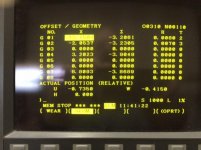
Here's the Offset screen indicating the radii and tool tip numbers.
Thanks for any help on this and I hope I've provided sufficient information. It will be much appreciated.
Cheers,
Rich
Gang lathe, Fanuc 0i Mate TB control, "rear" lathe (+x away from me, +z to the right)
Even though I've been working with this lathe for a couple years now I have never really needed to use radius comp until now. I have no CAM program so I hand code everything. The part is pretty much dead simple - it's a .728 OD, .628 ID ring with an external convex curve and a small internal concave curve at one of the lips. The stock is .750 x .600 tube.
Here's the code section that has given me an error: 041 INTERFERENCE IN NRC ("overcutting will occur ... modify the program" says Mr Fanuc). The red code line gives me the error. The tool tip number is T2 as it is a left hand profiler. I hope I have that right. The tip radius is .008
I have been poring over the Smid book on this subject and evidently I'm not understanding something about the tool tip clearance required, I think. The line in question is just trying to exit the profile and the retract motion in Z after that has more than the Tx2 clearance from what I just cut. I think.
What am I missing?
...
(EXTERNAL PROFILE)
(G41 LEFT OFFSET T2)
S#104 M3
T0101
F .002
G0 X-.770 (CLEARANCE)
G0 Z.030 (CLEARANCE)
G0 G41 Z.020 T0101 (ENGAGE RADIUS COMP)
G1 X-.700 Z0.0
G1 X-.735 Z-.032 (CHAMFER)
G1 Z-.415 (TURN TO CUTOFF LENGTH)
G0 X-.770
G0 Z.020 (BACK OUT FOR FINISH)
G0 X-.676
G1 Z0.0 F.001
G2 X-.718 Z-.046 R.071
G2 X-.709 Z-.350 R1.808
G1 Z-.415 (TURN TO CUTOFF)
G0 X-.770
G0 G40 Z.5 T0100(CANX COMP)
...
_______________
Here's the Offset screen indicating the radii and tool tip numbers.
Thanks for any help on this and I hope I've provided sufficient information. It will be much appreciated.
Cheers,
Rich