What's new
What's new

Line Boring Metal 3D Print

Novaguy

Plastic
Joined
Dec 29, 2022
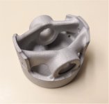
I have an Aluminum DMLS piston that I want to finish machine the wrist pin holes in.

DSC_2869 (2).JPG

They are 13mm wrist pins, which I spec'd at 12.75mm for finish reaming with a tapered hand reamer (I don't have large mill).

Since the part was printed from the top of the piston up, the OD of the piston is accurate, but the wrist pin holes are oblong and 12.4mm at the minimum.

The backside of the holes are angled so I'm reluctant to chuck it up in the lathe and line bore them. I'm not a machinist and would like to get this done without taking it to a shop...any ideas?

There is 0.5mm extra material on the OD of the piston so it would be machined in relation to the final sized wrist pin holes. So they don't have to be "perfect" just aligned enough to be able to slide the pin through.

1672362560797.png
 
You must have paid a good amount for that print, and you're saying you want to use a taper reamer to finish the pin bores and that pin fit that's "close enough" is good enough?

May I introduce you to Moonlight Machine? He's probably got a word or two for you...
$30 plus $30 shipping from CHINA. Quotes from the US and Canada are 10x plus that number. Is the quality the same, I have no idea.

I'm avoiding the best solution: taking it to a machine shop and paying more than the part is worth to do it...

That reamer is long enough that it "match drills" the 2 bores into alignment. The reamer I'm using is cutting pretty much on-size.

After opening the wrist pin holes, I can indicate in the piston using the pin and face off the bottom of the piston skirts.

DSC_2731~2.JPG

From there, I have a fixture made to machine the entire piston OD
 
I hesitate to join in on this but...you can put your reamer in the lathe chuck and clamp the piston to the top of your compound and ream away. You will have to be creative with clamps and shims to get the height aligned, compound may need to come off?
Thanks for a useful comment and great idea! Might take a bit of ingenuity but it could work...

Even if the wrist pin bores are reamed non-perpendicular to the OD, the OD will be machined down anyway. In theory, they will end up perpendicular, which is what really matters in this case.

It's an 80cc dirt bike piston for demonstration, not for an F1 car.
 
So a poorly machined piston will run in a dirtbike, but not in an f1 engine?

What alloy is this piston? Is it heat treated?

Correction: a poorly machined piston will run MUCH LONGER in a dirt bike, but not in an F1 engine.

The alloy is AlSi10Mg, not heat treated.

I've machined piston rings (on a harbor freight lathe 😲) for this clear engine cylinder I designed. I have a hunch this will also work....

 
Click bait for your YouTube channel. Should have known!
What is, the piston? Do you have any useful comments or are you just the PM Donkey lol?

I work nights, on an island, in the south - and I find this janky.
3d printed aircraft grade jank.
Not sure what this all this means... must be some southern-brother speak.

Porsche and Mahle have made 3D printed pistons for the GT2 RS for anyone interested:

 
Well, at $60 total (and the wait), I can't argue with experimenting. In fact, I'm a bit staggered at how cheap that is, but given the predatory nature of CN's economy I can't be surprised...
 
Hi Novaguy:
IMO there are some basic things you must determine about your piston to get an idea of what your order of operations needs to be.
I assume the wrist pin needs to be centered on the axis of the piston and must also be perpendicular to it in the plane of rotation.

In your opinion, how good does it need to be in order to be successful?
Do you need to get it perpendicular within a thou?
Within a tenth?
Within 10 thou?

How accurately must it intersect the axis of the piston?
Which is the more important consideration?

Once you are satisfied you know that (or have a reasonable guess) you can start to decide how to tackle it.

Two ways forward:
1) Machine the piston body first and locate the wrist pin bore to suit the body.
2) Ream the wrist pin bore first and align the turning operation for the body to the position of the bore you've made.

Either way will work if you spend enough effort on it but which you choose will determine how much fucking around you will have to accept.

A machine shop will almost always choose to turn the body first in order to have datums to fixture to.
They will then single point bore the wrist pin bores for location and then finish them to size, either by boring them or reaming them or honing them or whatever.
Easy for them to do because they have everything they need...you state that you do not.

The way you propose is concerning for two reasons:
a) it's difficult to get the wrist pin bores perpendicular to the plane of rotation of the wrist pin at the same time it intersects the piston axis while chucking it in the lathe.
b) you only have twenty thou per side to clean up the piston body...that may not be enough.

Additionally, reaming non round holes without pre-boring them is going to be a pig's breakfast, especially if you hope to hand ream them.
Likely the finished holes won't be very round, and it'll be very hard to hold size, especially if you hand ream them with a hand reamer in a tap wrench and the piston in a vise.
It's almost certain you'll bellmouth the reamed hole.

So, your way potentially creates problems for you, most of which can be resolved by adopting Rob F's and Nmbmxer's strategy in posts #5 and #8.
If you can clamp the piston to the lathe carriage, you can single point line bore the wrist pin holes to get them round and on location.
You can ream them to size, and though they won't be as good as a factory piston, they'll be miles better than a hacker ream job.

Your challenge is to mount the piston securely and accurately onto the lathe cross slide.
Do you have a way to do that?
Ideally you could find a way to bolt a 3 jaw chuck on to the cross slide.
Finding a way to clamp the piston to the toolpost will also work.

If you do it this way, it pays to turn the piston OD first so you can indicate off the OD and the piston face.
It's a pity you didn't come to us BEFORE you had the print made...if you had, I would have recommended having a cylindrical shank printed right onto the face of the piston to allow you to turn everything in one shot and then just chop off the shank when you face the piston.
I also would have encouraged you to leave a lot more stock on the OD.

Once you have the piston turned, you can set it up on the cross slide, clock it in and go to town.
With care you'll get it as good as the typical machine shop will get it, and it'll likely work about as good as you expected it to work.

If you decide you're going to try to do it the other way, you will need a four jaw chuck for the lathe so you can move the blank around to dial it in.
Put soft aluminum or copper shims on the jaws so you can encourage it into perpendicularity with a rubber knocker and then squeeze it into coaxiality with the four jaw.
Expect to do this a whole bunch of times before both orientations are very good.
Turn as much of the piston as you can, then flip it, clock it in again with the 4 jaw, and turn the rest of it.

So yes, it's definitely doable, and with patience in your setups you can even make it pretty damned good.
Good enough to look back on your work with pride.

Cheers

Marcus
www.implant-mechanix.com
www.vancouverwireedm.com
 
Last edited:
Well, at $60 total (and the wait), I can't argue with experimenting. In fact, I'm a bit staggered at how cheap that is, but given the predatory nature of CN's economy I can't be surprised...
My thoughts exactly! At that price, why not?

That $30 shipping was DHL - got here in 4 days...

I was more shocked at the pricing of metal 3D printing in North America. I figured a mostly automated process like DMLS would take cheap labor out of the equation. Seems to be mostly greed. The chinese machines are probably much cheaper as well.
 
Hi again Novaguy:
Last time I checked, an EOS DMLS machine was 3/4 of a million dollars and it had to go in a special room equipped for handling the hazardous powdered metals safely.
The metal feedstock was breathtakingly priced too.

You gotta make an awful lot of 30 dollar pistons every month to make the payments on the machine.

Cheers

Marcus
www.implant-mechanix.com
www.vancouverwireedm.com
 
Last edited:
Hi again Novaguy:
Last time I checked, an EOS DMLS machine was 3/4 of a million dollars and it had to go in a special room equipped for handling the hazardous powdered metals safely.
The metal feedstock was breathtakingly priced too.

You gotta make an awful lot of 30 dollar pistons every moth to make the payments on the machine.

Cheers

Marcus
www.implant-mechanix.com
www.vancouverwireedm.com
When I was working at the medical research facility almost ten years ago I tried talking my supervisors into getting an EOS, about $1/2M then. Didn't quite make it happen, but as you say there's a lot more to it then just the initial purchase.

If China can make good metal prints on machines in the $50K range and make a profit on sales like the OP's (and it's a solid, homogeneous part), then we've got some issues to worry about...
 
Last edited:
@implmex thanks for the detailed look at this project, regardless of how ridiculous it seems.

How accurately must it intersect the axis of the piston?
Which is the more important consideration?
The important thing is that the wrist pin bore is perpendicular to the OD of the piston. Otherwise, you'll destroy the bearing in the connecting rod in no time, and unnecessarily side load the piston against the cylinder wall.

For my purposes, within a thou should let this function long enough to demonstrate. It's not likely a 3D printed prototype will stay in 1 piece long at anything off-idle :D

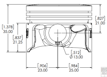
The wrist pin bore is offset 1mm from the axis of the piston:
1672422127133.png

I also would have encouraged you to leave a lot more stock on the OD.
In retrospect I do wish I left more meat on it than just 0.5mm! Any extra "volume" costs money...I considered leaving a cylindrical shank on the piston crown for chucking onto, but didn't expect to need it and wanted to avoid printing excess "support material". In my experience the print quality becomes reduced compared to printing on a flat base.

Additionally, reaming non round holes without pre-boring them is going to be a pig's breakfast, especially if you hope to hand ream them.
I agree mate. I'm just now seeing that the tapered reamer won't even fit into those undersize holes. Not a good idea to begin with but was within my means.

Those oblong holes will need to at least be started with an endmill or boring bar. The difficult part will be aligning those 2 bores concentric when the holes are so badly formed. I have a machinist buddy that might help out with this.

Here was the plan:

Once the wrist pin bores are machined to size, the plan is to indicate on the wrist pin until it is running parallel to the cross slide. THEN cut the bottom of the piston to form datum for the next fixture.

DSC_2731_2.JPG

With the bottom of the piston skirts faced off and parallel to the wrist pin, chuck it up in this fixture. I would turn the face of the fixture before mounting the piston to ensure it's true as possible.

Then machine the OD down and cut the grooves. Aligning the parting tool will be a challenge as well.

Typically, pistons have a taper to account for thermal expansion the closer you get to the combustion chamber, but I won't worry about that for this.
Capture.JPG

So yes, it's definitely doable, and with patience in your setups you can even make it pretty damned good.
Good enough to look back on your work with pride.
I think so too. I don't have a four jaw chuck but we'll see what I can do. Thanks for ideas!


Back
Top