What's new
What's new

Machining a rad using Y & C axis

Macrezz

Plastic
Joined
Sep 30, 2015
CMZ TXX66Y2 - Fanuc 31i

Hi floks. Please help.
Can anyone tell me if it's possible to swing a rad using C & Y axis?
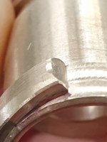
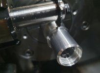
We use a 30mm saw blade held in a radial power tool, to cut small rads in between two lobes. Machining on top of the part.
I'd like to change the program from the eight C, Y points to using G2 and G3.
Is this possible?

Thank you.
 
Apparently a CMZ TXX66Y2 is a twin spindle, 3 turret lathe, according to the google machine.
Hi. It's the two turret version but has a Y axis and C interpolation.
I'm struggling to wrap my head around it because of cutting on top. X0, Y12
A straight X,Y rad isn't a great solution. Keeping the front cutting edge on X0 is what I'm try to do.
 

Attachments

  • 20220603_105009.jpg
    20220603_105009.jpg
    341.9 KB · Views: 41
  • Like
Reactions: Ox
Are you saying that there is no G2/G3 way of doing it?
In most areas of the cutter in your picture, it seems that the form of the cutter comes down to a relatively sharp point, but the one tooth towards the top of the picture seems to be flat on the face. If the form comes to a point, you should simply be able to locate the cutter in X and Y, then rotate the "C" axis.

Regards,

Bill
 
Thanks for the pic as I was having a hard time understanding your app.
Not that I can help with this app tho. (Maybe G16? ;) )


---------------------

Think Snow Eh!
Ox
 
Are you trying to do a radius entry/exit to your undercut between the lobes?
If I am understanding you correctly(big IF) I would try an entry arc in X and Y using G17 (ending at X0 and Y12), then rotate your C axis to the other end of the lobe and then arc out again in X and Y.
 
Are you trying to do a radius entry/exit to your undercut between the lobes?
If I am understanding you correctly(big IF) I would try an entry arc in X and Y using G17 (ending at X0 and Y12), then rotate your C axis to the other end of the lobe and then arc out again in X and Y.
.

Trouble is that he is at 12:00, not 3:00

But if the arc desired was actually produced, it would seem to be to be a hideous looking feature.
Concave with sharp corners.

???


-------------------

Think Snow Eh!
Ox
 
Thanks for all the replies.
A G17 X,Y rad doesn't produce the desired result. The front edge of the saw needs to stay on X0. Otherwise the thickness cuts the top of the part when it moves X minus to pick up the tangent.
The bronze pic is G17 X,Y
The plated pic is C axis.

If there was a version of G112 that moves on y instead of x I'd be sorted already.
What I'm asking is if there is a way around plotting a twenty point rad on C, X.
Beginning to think not unfortunately.

@GENERALDISARRAY
To have a one tool solution to cut the rads and clean out in between the lobes.
 

Attachments

  • 20220607_082756.jpg
    20220607_082756.jpg
    136.4 KB · Views: 15
  • 20220607_082913.jpg
    20220607_082913.jpg
    536.6 KB · Views: 15
Are there some parameters you can change to swap Y and X axes in the control so you make the machine think the Y is X and then can use G112 with the Y? You can have the program change parameters. It's a long shot, but I can't think of any other way. I'd just use the points like you're doing.
 
Emailed CMZ about using Y axis. Still waiting on a reply.
Got it sorted thankfully.
Programmed the left rad in the photo and separated the clean out path from the rad path.
Was trying to program the right rad initially
Cheers.


N13(SAW CUT LOBE RADS)
(30MM SAW - RADIAL TOOL)
(CUTS AT 90 DEGREES)
(SET X ZERO TO SAW FACE)
(SET Y ZERO TO SAW RADIUS)
#940=1.45(SET SAW THICKNESS)
M05
M98 P10
M80
G28 H0
G50 C0
T0606
M83 S2250
M08 M368
X0 Y14 Z30
G17
(RIGHT LOBE LEFT RAD C-30)
(H-10.757 =1.94MM RAD C VALUE)
C-40.757 Z-28.5
Y12.5
G1 Y12.25 F.2
G2 X3.87 Y10.19 R1.94 F.015
G0 Y14
(LEFT LOBE RIGHT RAD C34)
C44.757 X[0-#940*2]Z-30.25
Y12.5
G1 Y12.25 F.2
G3 U-3.87 Y10.19 R1.94 F.015
G0 Y14
(CLEAN BETWEEN RADS)
C34 X[0-#940*2]Z-27.3
Y12.5
G1 Y10.375 F.1
Z-30.25
G0 Y14
C-30 X0
Y12.5
G1 G107 C10.4
Y10.375 F.1
Z-27.3
H64 X[0-#940*2]
Z-30.25
H-64 X0
G107 C0
G0 Y14
Z30
M98 P10
M01
 

Attachments

  • 20220609_101728.jpg
    20220609_101728.jpg
    677.5 KB · Views: 2


Back
Top