nineandtwothirds
Plastic
- Joined
- Jan 22, 2019
Hey all,
I posted recently about the Mitsubishi Freqrol Z300 Model FR-Z320-7.5K-UL inverter in my 1992 Fadal VMC 40.
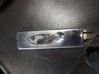
It seems the brake resistor has been getting wayyyy too much current, enough to melt its aluminum housing (see pic 1) and create a fair amount of smoke.
After testing, all of the IGBT modules are good. Good diode readings and no shorts from gates to anywhere on all 3. Capacitors all seem good as well. Even the melted brake resistor is giving me a good resistance reading.
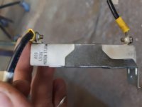
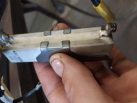
There is another micron 17.H ceramic or cement resistor that bridges the two sides of the contactor. Numbers read 40B 1.5K ohm (see pic 2). When checking this resistor with an ohmmeter in the 200 ohm range, I'm getting a reading of 1.9. That's well outside a 1% margin of error. But I don't know what the function of this resistor is and if it could be the source of my problems. There does seem to be some scorching near the terminals (pic 3).
Here are some machine symptoms that I have noticed over the past couple months that have been intermittent with slowly worsening regularity:
1. Upon startup of machine when warming up the spindle, I always get a spindle drive or control fault on the CNC readout. After ~30min of letting the machine sit, powered up, I can start the spindle no problem. It should be noted I don't have a parameter unit for this inverter, so I'm not getting codes from it. But every time I get the spindle drive or control fault, I have to reset the inverter as the alarm light is on.
2. Upon startup of the machine, I have been hearing more and more clicks, seemingly from the inverter and likely from the contactor, as it's the only moving part. When it started smoking, it was clicking like crazy. I have disassembled and cleaned, and tested. All looks good. But the contactor is what is controlling current to the brake resistor.
3. Every time the spindle starts up, during a program or just manually, I get a surge on the power gauge on my CNC display (pic 4) going up to almot 90% and then dropping down closer to 40% under no load and staying around there during cuts.
4. Roughly 1/20 times the spindle starts, usually during a program, it struggles to get going. The first time it happened, I ruined a tool. I have since programmed dwells after every spindle start in a program to prevent that from happening again.
To me, these ALL seem related to the brake resistor. But I'm open to opinions. I also really want to know what that micron resistor that's bridging the two sides of the contactor is doing.
All help and input will be appreciated.
Thanks,
Mat


