What's new
What's new

Modifying Monarchs problematic oiling system.

Addressing the Series 61 worm gear assembly bushing issues I discussed in post #15.

Funny side story in relation to this thread. On the 61 apron I repaired the clutch lever assembly first. It had a zerk fitting that someone had previously shot grease. In the repair I stamped the face with "oil only":
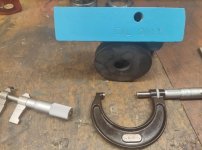
243.jpg

So I had those particular stamps handy when I removed the worm gear assembly. Taper pins hold the bushings of worm gear in, so I wanted to keep them in order. So I used O, I, and L on the 3 bushings :D. Yeah, stupid I know, sue me. The "L" stamped bushing I replaced with one from Mike Thomas, But I stamped it L too, to keep track of what I was doing. Can still just barely see the stamps:

244.jpg

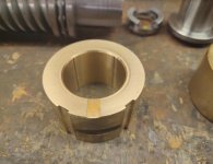
I bored the 3 old bushings. Sleeved them with c932 bronze. Bored each to its respective shaft. One modification was to add 4 oil channels to the ID of each. The two outer bushings the channels go half way through to reduce oil leakage. The center bushing has oil on both sides, so I punched the channels all the way through.

Another modification was to the bushing for the drive coupling. To the right you can see the old bushing with wear to the thrust face. On the new bushing I milled 2 oil reliefs on the thrust face. Above the bushing is the drive coupling that slips inside. It thrusts directly onto this bushing. The mod will extend bearing life:

245.jpg
 
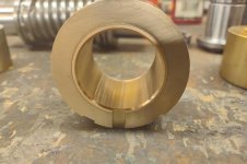
The next modification to the Series 61 worm gear assembly, is to the center bushing. Again, you can see I cut the 4 oil channels all the way through on the center bushing. Oil needs to be on both sides of this bushing.

And as oil needs to be on both sides of the bushing, I cut 2 oil paths to the bottom side of the bushing, straddling the taper pin notch. These two paths will allow oil to fill the chamber next to the worm gear, where the drive coupling and its bushing are. The additional benefit is oil can now be drained from the chamber as well, when oil oil is changed:

246.jpg

With the taper pin more or less at 6 oclock, those two paths are not directly on the bottom. But this is still a great alternative to the big fat nothing it had previous.

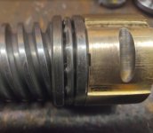
The next mod is to the face at 6 oclock. I added an oil path there to the lower bearing surface. While I think oil may get there anyway, the thrust bearing may interfere. This will be even more so if the thrust of worm gear is at zero, which should be done with this style of bearing:

247.jpg 248.jpg

My current intention is to set oil level in worm gear assembly to at the lower bearing surface, or just a hair above it.
 
Ouch, that hurts!

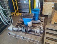
Went to a tug boat outfit's main yard in Galveston today. Walking into their shop, lo and behold, a worm gear and worm wheel. I'm wondering if I can make it work for the 10ee. Might add some weight though. . .:D

255.jpg 254.jpg

That assembly is for a capstan on the front of a tug, for pulling heavy lines in. That worm wheel diameter is about 3'. Check out those teeth:

256.jpg
 
Test 1, part 1 of 3.

Testing carriage and cross slide lube system with a Bijur one shot pump. All metering units have been totally gutted of internal parts, They are just open fittings now.

Got the dial installed as it too has a lube line. Getting set up with the Bijur pump was easier than expected, but I had done the majority of the work more than a year ago. Original oil supply from apron has been capped off.

I just set the pump on cross slide for the test:

257.jpg

Line connected here. I'll pretty that up with something different on final assembly. There's atleast 7 feeder lines, but I'm thinking its 8.

2 for rear flat way
2 for vee way
2 for cross slide
1 for flat way
1 for dial

258.jpg

I installed the gib on cross slide, but left it dry. I also moved carriage back and forth to wipe residual oil off, from when I set that on.

259.jpg

Then I began pumping. It took 6 pumps to get air out of the system and to just begin seeing oil:

260.jpg 261.jpg
 
Pat 2 of 3:

The front flat way, also after 6 pumps:

262.jpg

Though I had oil, I was not fully lubed yet. I pumped two more times bringing it to 8 total. That got me fully lubed at each point of the whole system. Here we can even see the short shaft for dial/cross feed flooding:

263.jpg

Side note: The short shaft through dial base felt super nice once oil pumped through. I got just a little felt resistance in spinning it, plus zero play in the shaft.

Some of the other lube points:
264.jpg 265.jpg
 
Part 3 of 3:

Now just being obnoxious, I pumped 4 more times, bringing the total to 12. I was simply flooding and drooling everywhere:

266.jpg 267.jpg 268.jpg

So it took 8 pumps from an empty, air filled system, to be fully lubed. Now that it has been lubed and air pushed out, my expectation is it will take 4 pumps to fully lube from this point on. And probably only 2 or 3 if pumping within the same day.

Now on a Series 61 I have more real estate than a 10ee. Currently I'm thinking I could mount a one shot on the apron with a discreet oil line running up and toward my connection:

269.jpg

I discussed some of this more than a year ago. At that time, Bill H thought mounting off the TA would be the best bet for a 10ee. His comment here:
Getting a Monarch Series 61 Back in Service

Test 2 will come tomorrow. I'll wipe down and see how many pumps to lube everything, now that air is out and system primed.
 
Test 2 complete on day 2.

I wiped down, sliding cross slide and carriage to wipe oil off.

It took 2 pumps of the one shot to just begin pushing oil at cross slide. By the 3rd pump I felt everything has begun to get oil. And I felt really comfortable that at the 4th pump I was well lubed at all points. So it does indeed work well.

I had more pics, but with lighting not all came out well for visuals. The vee way we can see clear in the pic:

270.jpg


If I had an adjustment to make, it will be to the front flat way. The front flat of carriage should not sit on the ways. Its close, but should not be fully down and touching. On my 61 I have about .010" gap between carriage and the bed.

One oil line feeds the front flat. And I feel the oil there is a little bit excessive. This is after four pumps, and then sliding carriage:

271.jpg

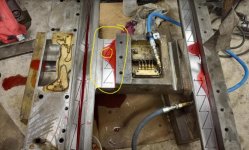
Now mllud22 mentioned to me about regulating for greater efficiency. On this one oil line I will do that. Here's a pic of the saddle upside down when I got the lines cleared out. I circled the front flat, and its oil hole in yellow:

272.jpg

I will be lifting the saddle again for dealing with the way surfaces. When I do, my plan is to drill that oil hole a little larger and hammer a brass plug in it. I'll then drill a hole in the plug maybe half the size of the original hole. Example, if the hole was .080", then I'll drill the new hole .040", or there abouts.

Bottom line though, it works, and works without the metering units. With this more thoroughly answered, I have a more complete picture on how I'm going to handle the apron lube system. Some details of that will probably be a few posts down from this link:
Monarch Series 61, Rebuilding for Improvement
 
Last edited:
This is all really interesting. I've had a 16 CY refurbishment waiting for me for a couple of years now. I've gone through the apron and had the bed reground. I ordered all new metering pumps for the saddle but have yet to install them. I've been toying with the idea of adding bullet oilers to the saddle. I have a mid 30s reed prentice with a completely manual oiling system and i love it. 5 minutes with an oil can before i use it and i'm good to go. Has anyone actually added to bullet oilers or is it just a notion struggling to become an idea?
 
This is all really interesting. I've had a 16 CY refurbishment waiting for me for a couple of years now. I've gone through the apron and had the bed reground. I ordered all new metering pumps for the saddle but have yet to install them. I've been toying with the idea of adding bullet oilers to the saddle. I have a mid 30s reed prentice with a completely manual oiling system and i love it. 5 minutes with an oil can before i use it and i'm good to go. Has anyone actually added to bullet oilers or is it just a notion struggling to become an idea?

If you already bought the metering units, you may be better off just installing them. Especially if you went through apron and I assume have a new filter on the oil pump.

As I was starting from scratch, I wanted to eliminate them as I truly think long term they are bad for a machine. But new metering units and clean oil might last you 20 years.

I believe Cal installed ball oilers to his saddle, but the intent was pre-lube and as insurance to the regular oiling system, as I understand it anyway. I forget where I saw it, or I'd link it.

Not sure where you are in your rebuild though. If the bed was reground, is the carriage raised and scraped in yet, or where you at with it ? If its still off the machine you could go either way with the lube system imo. Install the metering units or not, use a one shot or not. Might even use an oil can but with a grease gun hose attached, and a zerk fitting as your inlet. But I'd want to test that before committing.

Just a real rough estimation on my part. I'd guess new metering units would get me 20 years before I need a major maintenance again. Without metering units, or having them gutted, I think I can get 50 years out of it. Where I might only need to change oil pump filters every 20 years depending on oil, verse tearing the machine down to the ground chasing those pop fittings.

My other consideration was who gets the machine after me. Most people want to use the machine, not rebuild it. Will they know all the maintenance tricks ? Or can I simplify it to where even a dummie can just check oil levels.

Great Feedback, thanks. When i had the bed reground, i also had the saddle milled in preparation for turcite. I also had the cross slide dovetails ground and the cross slide flat bearing surface milled. The guy that did the work did not have the proper grinding wheel so we discussed getting it close with his mill and i would then hand scrape the rest. When i went through the apron i changed all the bearings, replaced the worm and wheel (which left a dent in my wallet) changed the oil pump filter and did a braze build up on the oil pump actuation arm to restore full travel. I did a test and the pump functions well. I'm 60, and retired so my machine will get occasional hobby use. Sounds like i'll be pushing up daisies long before the metering valves become a problem. Thanks
 
A bit of a side quest here. I really like the old style Bijur one shot. It has an aluminum tank with site glass, plus a larger gits to fill it.

The newer one shots come with a clear plastic tank, and what looks like a plastic fill cap.

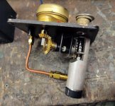
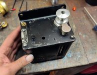
Been keeping an eye out for the older style. Decided to take a chance on something. Not a one shot, but an electric cycle timer type. I don't want to use the electric, but next to the electric motor has a lift knob to operate by hand. Found one, with old style tank and priced right. The model is a c2803.

The plan being to remove the electric motor and just use the pump by hand.

273.jpg

You can see the pull knob behind the gits oiler:

275.jpg

Lifting the lid, the motor and mechanism is pretty simple:

274.jpg

After the motors mechanism is removed. Also note the base where filter goes is smaller:

276.jpg

Top side not too terrible, but need to fill a few holes:

277.jpg

I cut a new felt filter and installed. Tested the pump by hand. It works, but the discharge volume was less than a regular one shot.

I hooked it up to the saddle the same as I did the one shot, but it was taking a lot more pumps. And I did not feel this particular pump was a good fit for the Series 61.

Now I grew a brain and looked up some specs. A new style Bijur one shot has a max discharge of 5cc. The knock off brands claim 8cc. Not sure what my old style is, but guess at least the 5cc.

Now the model I just striped the electric motor. . . 1cc per motor cycle. Pulling the knob gives more than the 1cc, guessing 1.5 to 2cc. But its not enough. The regular Bridgeport style one shot is the way to go, at 5 to 8cc.

Specs on a Bridgeport style one shot, it says 1 to 5cc because travel of handle is adjustable:
L5P-R Pump - K1099 | Bijur Delimon International

Spec on the electric motor type:
TM-1 Pump - C2803 | Bijur Delimon International

What I may do is buy a new style but use this tank with it. Or pick up the knock off version and use its pump with this tank assembly.
 
I wanted to get any drilling and tapping done to the apron before going about its final clean up.

I started with the drain to the worm gear sump. I drilled it larger and tapped to 1/4" pipe thread. The pic is not the fittings I'm using, but just what I had on hand to sort out lengths and heights. I'll be looking to get the site glass closer to the apron. Here's looking at the bottom side of apron:

278.jpg

With this set up it has me in the right zone for height, as I want oil level to the bottom edge of the ID of bearing:

280.jpg 279.jpg

I swear I'll install it straight on final assembly. Little crooked in the pic though :D.

281.jpg

I'll be installing a one shot pump in this assembly, but I wanted to get the mounting sorted for drill and tapping:

282.jpg
 
Continuing to work on the apron of a Series 61, not sure if this portion is the same in a 10ee or not. But I removed the two clutch lever assemblies:

284.jpg

Why I'm posting in this thread is looking at the thrust bearings located inside, as part of the shaft assembly. Any oil that manages to be inside the clutch lever housing, will be below the OD of these bearings. We can see the red color from condensation caught inside there:

285.jpg

Looking inside the clutch lever housing there's a step where a part of the shaft butts up to it. Easy enough to figure out a measurement as to where thrust bearings are located inside:

286.jpg

With that measurement I drilled a hole through both housings to add a gits oiler:

287.jpg

The gits is located directly over the thrust bearings. Shooting oil in will drop the oil right onto the thrust bearings. Looking inside you can see the new oil hole close to the step:

288.jpg
 
Nearly complete with the apron build on the series 61, and looking to finish the lube system there.

Next mod is the oil line that fed the worm gear sump. I no longer need that there, as I will lube the worm gear separate, and use a sight glass there. Luckily the copper line was long enough to redirect to the inside, and to one of the higher shafts that would naturally see less lube.

I drilled a hole in the back of apron, and redirected line to the upper clutch assembly there. I will fill the oil in apron and run a lube test. Depending on results, I may move that line to point at the small thrust bearing, of the same shaft:

314.jpg 315.jpg

Now starting on oil pump mechanism. I removed oil pump. This teeter lever drives oil pump by way of a piston pin on bottom side. Each side of the teeter lever rides on a large cam lobe, one cam lobe off the gear for apron hand wheel, the other off shaft for worm wheel. Not too much wear here. Got it cleaned and lubed up:

316.jpg
 
Now getting on to the oil pumps. The Series 61 has three oil pumps, nearly identical except for the mounting on each. While I don't 100% know, but I'm pretty sure the pumps are a Bijur product, not Monarch. Too similar in design to the one shot pumps.

Thanks to Harry Bloom, aka beckley23, for the "another new toy" thread. It gave me some idea about the pumps which helped me prepare. Including buying F5 felt as he did to cut out my own filters. In his thread he begins the pumps about here:
Another New Toy

Again the pumping volume and actual pump appear identical on all the Series 61 pumps. One pump in apron, one pump at lathe's left gear end, and one pump for the head stock.

Here's the apron's oil pump:

317.jpg

Following Harry's foot steps, I tested the pump on the bench. What caught my eye was how little volume it actually moved per pump. My eyeball guesstimate figured it was equivalent to 2 or 3 large drops of oil. Seemed quite small compared to a one shot pump's volume.

I was a little concerned that something was wrong with the pump. But examining a little more closely, its just the design and specs of the pump. The internal shaft is the piston, it does not get larger inside pump. We can see the shaft/piston size here. The OD of the shaft is about .153". The max stroke is about a .500", though the cam lobes are not that tall:

318.jpg

The pump has two ball type check valves, one on the suction, and one on the outlet. Here's the suction side, easy to removed with a flat head screw driver:

319.jpg

Check valve removed, and seeing the lower side of shaft/piston bore:

320.jpg

The pump body is easily removed. Though I don't see a reason to do so, no seals or orings:

321.jpg
 
Again, using Harry's recommendation in "another new toy" thread, I choose F5 felt for the oil pumps, vs buying a kit. He mentioned he thought 3/16" felt was too thick, so I opted for 1/8" thick. I picked up a 12" x 12" sheet from Grainger. Here's the tag on it:

322.jpg

Harry went so far as to make a large hole punch to cut out his felt filters. I find felt cuts real easy with a razor blade or scissors. So what I did is dip the suction end of pump in oil, and used it to mark the felt. Then I cut it out with scissors:

323.jpg

I cut all the pump filters now. The headstock oil pump I will address when I get into the headstock. Right now, I'm servicing the left end oil pump, and the apron's oil pump.

Here's a look at the pump filter pieces of two pumps. The screens were made of copper or bronze, and easily cleaned. One screen is course, and the other very fine. The course screen is actually pretty fine as well, but the fine screen is ultra fine.

I'm of the opinion the fine screen is more critical if you intend to use Bijur metering units. As the metering units have their own filter that is quite small, i can see the triple redundant filtration before them, to help protect them. However, I am gutting my metering units of internal parts, so I prefer to leave the ultra fine screen out, as it is the most easily clogged part. The felt and course screen will be enough for my purposes.

324.jpg

Two pumps finished. The 1/8" thick F5 felt did the trick. Real nice tension from retainer and locking ring, had just the right feel to get it locked.

325.jpg
 
Probably the last modifcation to the apron's lube system, I'm gutting the bijur metering units of internal parts. The bottom side of apron near the oil pump, a manifold is mounted with 4 pop fittings. Here's the manifold:

326.jpg

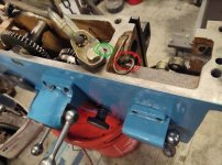
Besides the 4 in the manifold, there is one more related to the apron itself. It feeds half nuts, and normally the worm sump. I circled it in red. The green circle is the feed to carriage. I have already plugged carriage side, but I will make a brass plug to hammer in apron side as well:

336.jpg

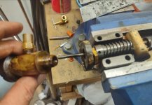
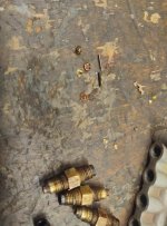
With the metering units removed, you clamp the small black portion in a vice, and work fitting off of it. Then clamp fitting in the vice. Using a drill, go in the opposite side the black piece was installed. The drill will pull the felt filter out first. Once the felt is out, keep drilling straight through. With little effort soon the drill will push the check valve mechanism out the side the black piece was installed.

Here's a look at some of the pieces:

327.jpg

Once the fitting is cleared, blow it out. Then reinstall the black end so the oil line will seal proper.

With it done, you can see through the fitting:

328.jpg

Once I get the oil pan back up, I'll fill with oil and run a test to see how well oil transfers across the gears and flows though lines. I'll do this test with the apron sitting on a cart so we can get a good visual.
 
On the old L & S Model X lathe I had, the Bijur oil pump, just like the one in your picture, supplied oil to the entire carriage including the apron. The problem with that was, the upper carriage, cross slide was not getting oil. Of course there was more to the story that I won't go into here. I took and isolated the apron from the saddle and cross slide and let the apron oil pump provide oiling to the apron only. For the carriage, saddle, cross slide, taper attachment, I installed a electric oil pump, similar to the one your using. Wired it into the motor circuit so when the motor was running, the oiler would cycle and dispense oil about every 15 minutes I think it was. Worked out great. The only real problem was it sometimes dispensed too much oil. I did cut back the amount dispensing to almost a trickle and still dispensed a lot more than I wanted. For me to get to all of the metering units buried in the saddle of that carriage and change out to smaller units, wasn't going to happen!

Nice job your doing there. Thanks for sharing. Ken
 
Test and report, part 1 of 2:

The good news:
1. The sight glass and oil pan don't leak
2. Oil transfers across all the gears
3. Oil pump pumps (with a caveat)

Other news:
It seems I need oil level a little higher than the sight glass marker of mid way

Got the pump and manifold up:

344.jpg

Pan is not up in the next pic, but its good for reference. The red line is about where the top of suction filter is, and should be below the oil level. When doing my first test, with oil level midway on glass it seemed the pump was not pumping. I was rolling the hand wheel for several minutes and nothing.

I added oil to raise the level near the top of sight glass, just below the upper vent hole, marked in green in the pic. This seemed to do the trick. Afterwards the pump pumped.

Now either the top of suction on pump was sucking air, or maybe it was air bound ? Not sure. The only other possibility I marked in purple in the pic. The out going check valve is at 12 oclock, and potentially above the oil level. I know the line and fitting are tight to that out going check valve. But they are also brass or bronze parts so I didn't wail down on them super hard. Maybe sucking a little air ? Not impossible, but I put it less likely. I just wanted to make note of it as a possibility:

345.jpg

Funny thing though, checking the manual, 16" & 20" series 61 aprons call for 3 pints or 1.5 qts. I later drained the oil into a clean empty jug, and I figured thats how much I drained out. And that's with me filling toward the high side of site glass.

350.jpg

Rolling by hand, using the handwheel and both clutched engaged. Real nice oil transfer across the gears, which also gets into the clutches and most of the bearings. Makes me think the apron itself would survive even if the pump does not work. Note all the wet gears:

346.jpg

This hole is for the saddle oil feed. I will plug this hole, but for the test I just wanted to confirm oil was pumping. And it is pumping, you can see where oil has risen out of the hole:

347.jpg
 
Test and report, part 2 of 2:

I absolutely cleaned the oil pan, pump, and bottom of apron from sludge. I also hung the apron over a safety clean tank and washed it out on initial tear down of lathe. I didn't fully tear down apron, but did remove some components and cleaned. I left most of the bearings, gears, and shafts in place.

I filled with clean oil, and ran the gears by hand wheel for about 10-15 minutes, clutches engaged to turn everything. I noticed the oil was a little bit dirtier than when I just poured it in. I go out to eat with the family, gone for several hours, so the oil has time to soak in. I return and run the hand wheel for maybe 5 minutes. Let it sit a couple more hours. I now run the hand wheel for about 30 minutes.

The gears, bearings and such look much nicer, but the oil has darkened up. I drained the oil into a clean empty jug. Not that I need to tell you, but the left is the jug I drained into:

348.jpg

I'll rerun another clean batch of oil through it probably for another 30 minutes, and dump that too. At that point I'll button up the apron and call it good to go.

As much as it pains me to do so, I'll probably pull the site glass and move the marker toward the top, instead of leaving it in the middle. But I'm going to do another test with the new batch of oil to confirm oil level.

Another note. The bearing for worm wheel leaks slightly into the worm gear sump. Its the only oil leak I have, and as far as that goes, well its leaking into an area that I expect to use a little oil. Not necessarily a bad thing imo.

349.jpg


Back
Top