What's new
What's new

Modifying Monarchs problematic oiling system.

Test 2:

Well I think I realize what was going on with the pump and oil level. When I first began the first test I was only using the hand wheel, no clutches engaged. Later I engaged both, and raised oil level a little.

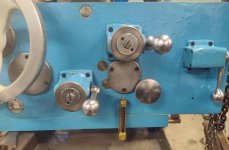
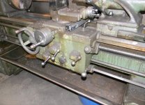
Well if you look at the apron, there are two cams that run the pump about here:
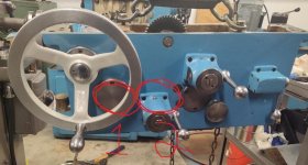
360.jpg

It takes 5 hand wheel turns to rotate cam 1 once, in other words one pump of the oil pump.

Cam two is naturally turned by worm wheel, though not directly on worm wheel's shaft. 2.5 turns of the worm wheel to rotate cam 2 once.

By engaging the lower clutch I can rotate both cams with the hand wheel, but cam two spins much faster. Cam 2 spins one revolution to 1.25 turns of the handwheel.

Anyway, I filled oil the 2nd time, to just a hair over the site glass midway marker. And the pump pumps.

As a follow up to the dirty oil. I filled with new oil and ran about 15-20 running apron by hand. Let it sit a couple hours, and ran it another 20 minutes or so. I drained this second batch of oil also. It was much improved over the first batch, but I could still see some off color to it.

I will fill with new clean oil and roll with it. I'll probably run the machine 6 months to a year, then drop oil and replace the pump filter again. As it is now, I think I'll be in real good shape.

One thing i forgot to mention in the last test was the gits oilers I added to the clutch lever housings. I did that to lube the thrust bearings there. But it has had a side benefit of making the engage/disengage operation real nice, the internal plungers just feel like they're lubed now.

361.jpg
 
Working to get the worm gear assembly installed.

I first wanted to know how much oil to put in. With worm gear and thrust washers in the way I would only be guessing at the level.

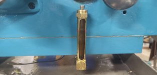
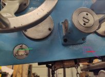
So what I did next was to install the new sight glass for the worm sump. You can see how it looks, plus the fittings I used. I put a 90 fitting with a plug toward the rear to be able to drain oil in the future:

362.jpg 363.jpg

I then partially installed the two outside bearings, to either end of worm sump:

364.jpg

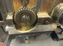
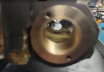
I then pushed the taper pins in the holes so oil won't leak out. I then use a No 98 level to level the apron, both long and cross. With apron level, I added oil, bringing oil level to bottom edge of bearing surface. Worm gear left out, so I could actually see the level (that big white circle is light reflecting off oil):

365.jpg

Now with oil level where I think it should be, I marked indication lines in red paint on the sight glass:

366.jpg

That silver socket head screw in the top of sight I added. I wanted to put a gits, but there is a drilled air vent passage in the top of sight glass. So I needed to drill a smaller OD. I drilled and tapped a #10-24 thread, and chamfered the top. Removing the screw will allow me to shoot oil in from my oil can. It works, I tried it :D. At some point later in my life I might make a nice thumb screw to go there.
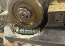
 
Test 3: Checking the worm gear lube.

Finished installing the worm gear assembly. Wanted to test how well it lubed, whether it leaked, etc.

One side note: After hammering taper pins in the 3 bushings, I was a little tight on the center bushing, I could spin it by hand, but I had a little stick/slip there. I'll go into more detail in the rebuilding thread about a post down from here:
Monarch Series 61, Rebuilding for Improvement

But due to that I swapped lube during this test. I started with DTE Heavy. With worm gear and coupling now installed, the sump holds a surprisingly small amount of oil to get to the fill line, maybe 2 or 3 shot glasses of oil.

I used an electric 1/2 drill to turn the worm gear from the coupling. This is low to medium low speed:

370.jpg

This medium to medium/fast speed:

371.jpg

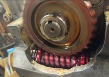
Looking from the qcgb box side, I could spin low to high speeds in clockwise direction and not loose a drop of oil. However, medium to high speed in counter clockwise rotation, oil trailing the thrust bearing would begin to get up on the ledge and run down, externally. Again with DTE Heavy.

Now going back to my center bearing being a little tight. I could spin by hand, but had a spot I could feel it tighten. Running with the drill it was smoothe, no tension or anything wierd. And using the drill to spin helped loosen it up some. But I still had some tightness I could feel by hand.

I drained oil, ran ATF in it with the drill. Drained again. New ATF again. And ran quite a bit in both directions with the drill, probably 40-45 minutes. This helped quite a bit, with ATF being a little thinner. I'm thinking I'm going to leave ATF in there probably 6 months to year of use and let it break in more.

Another nice thing about ATF, it has better visuals :D. This is high speed in a clockwise rotation:

372.jpg

High speed in a counter clockwise rotation. You can see fluid catching on the edge and running down. ATF being thinner had better results in this regard. I could run low and medium speed without any oil getting up on the edge, only high speed did this, and I'm not sure I'll ever have the feed rod turning this fast.

373.jpg

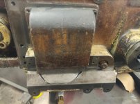
Taking a look at the chip guard, its not fluid proof. But I'm thinking to either add a small barrier on the edge of apron, or a seal of sorts to redirect any oil that gets on edge back into the sump.

374.jpg
 
I've never had the nerve to try this in a machine tool, but synthetic oil does wonders for transmissions. Someone should experiment with that ... from reading, btw, the thinnest you can run without breaking through the oil film is the best. Modern oils should be able to drop down a step in weight, as they lubricate better and don't break down as easily ?
 
I've never had the nerve to try this in a machine tool, but synthetic oil does wonders for transmissions. Someone should experiment with that ... from reading, btw, the thinnest you can run without breaking through the oil film is the best. Modern oils should be able to drop down a step in weight, as they lubricate better and don't break down as easily ?

I hadn't thought about synthetic oil, but I was considering some #10 spindle oil, which I have on hand. Just to try and see how it feels anyway. With the apron hanging in the air its pretty easy to change oil and experiment a bit. And having looking it up previous, the spindle oil is a little thinner than ATF.

I really think that center bushing will be fine, its just one of the OCD, annoying things that will gnaw on me unless I address it :D. Which I will mostly likely do. I'm just going to give it a day or so to see if it gets a new attitude.
 
Hey TGT,
Revisiting this as I warm up to work on my saddle and carriage (10ee)
Thinking about any mods that would better fit my use (sits dormant for long periods, then gets short spurts of use).
Want to be able to manually oil on start ups...

Question about the worm sump:
Like the site glass.
Why not just bore a drain hole in the back of the worm sump to drain back into the main sump, locating it at the level you want the oil to remain?
Thought that's where you were going with this at one point.
Did I lose the thread?
 
Question about the worm sump:
Like the site glass.
Why not just bore a drain hole in the back of the worm sump to drain back into the main sump, locating it at the level you want the oil to remain?
Thought that's where you were going with this at one point.
Did I lose the thread?

I did actually consider drilling from worm sump into apron's main lower area. I'd be lying if I could tell you with 100% certainty :D, memory is fuzzy. However I do believe the actual fluid level height for both would have been wrong, for one or the other.

Keep in mind, my first go at this is on a series 61, not a 10ee. So maybe I'll find something different on a 10ee, or the CKK 12 I intend to do as well.

But if I recall correctly, I measured from the middle site glass on aprons face, using that measurement I measured from rear, and worm gear. And if I recall, the level would have been higher in worm gear area than I preferred.

Depending which size lathe, the exact situation is a little different, but oil can and does lube the feed rod, and weep out there. There is no seal there. Having an oil level in worm gear area higher than feed rod will cause it to continuous leak, even when shut off.

So on a 10ee, I would want oil in worm gear sump to be at the bottom of bore of feed rod bearings. No leakage when machine is off. Off the top of my head, I think apron's natural fill height to middle of site glass is indeed higher than feed rod, or atleast higher than the bottom of bore.

So keeping them separate allows maintaining proper level for both.
 
Getting to the point where I’m ready to visit this issue on my 612. It originally had an electro tracer. This means, even with the tracer gone, the apron doesn’t lube the carriage and cross slide. There was a motor and clutch in the rear of the cross slide that ran a typical monarch rocker pump even with the clutch disengaged. Since the tracer is gone, no need for the motor which was disconnected when I got the machine as part of gutting the tracer. So I’m looking at a one-shot oiler.

I’m of the mindset to use a machine a bit before digging into rebuilding, so I’ve just been using a oil can when I need to use the 612. Most of my day to day lathe work has gone on my 1944 12”CK, which unlike the 612 has a DRO. One for the 612 is on the list.
 
Thanks TGT.
Having an oil level in worm gear area higher than feed rod will cause it to continuous leak, even when shut off.
That was what caught my eye when I re-read your thread.
I’m on board with the - “well lubed without waste and mess” - plan.

Liked your sight glass solution.
Pondering if there was another way to skin the cat.
I think apron's natural fill height to middle of site glass is indeed higher than feed rod,
Makes sense now why you had to go site glass. Woulda flowed wrong direction and left you too full…

I’m looking at a one-shot oiler.
Going into the clean up on mine, I’ve got this as a leading candidate. Im not as religiously opposed to bijur fittings as TGT… but I want a solution for getting oil to the carriage/ cross/ and compound. Have some ideas. Will wait till I have it apart before I decide best path.
DRO. One for the 612 is on the list.
This is on my list for the 10ee.
I have a mill that was cnc - now manual - will turn it into combo.

In order to utilize now - added DRO.
Inexpensive.
Off shore brand.

Accuracy and operation are shockingly accurate.
I plan to buy some additional sensors and magnetic strips, and take the brain/screen and install on my 10ee.
(Existing sensors and magnetic strips will remain on the machine and be used for the cnc).
 
I need to look at the feed rod location of my 60. I believe it is higher than the sight glass line. I wonder if the addition of the lead screw reverse shaft on the 61 moved the feed rod down and created a problem that didn't exist with the 60 engine lathe. Dave
 
I need to look at the feed rod location of my 60. I believe it is higher than the sight glass line. I wonder if the addition of the lead screw reverse shaft on the 61 moved the feed rod down and created a problem that didn't exist with the 60 engine lathe. Dave
I could be wrong, but I don't believe lead screw reverse lowered the design of other shafts. On engine lathes I've seen, the holes in apron are capped off for where LSR would have gone.

On series 60/61 feed rod does not actually ride in bushings of apron, worm gear does as it has little shafts on each side. 10ee's dont have those shafts on worm gear, so for those, feed rod itself rides on bushings.

I went out and checked, and on my 61 apron oil level marker is about a 1/4" to 3/8" higher than the marker I put on worm gear site glass. I also have some old pics:

345.jpg 366.jpg
 
Your apron is also a little different. The bottom tray extends below the casting and is shorter than the bottom length. Mine has a lower area on the right so the tray is level with the bottom of the casting. there is a hole in the casting that looks to have grease in it but is evidently separated from the rest of the apron since no oil drips from the hole. Dave
 
...

Question about the worm sump:
Like the site glass.
Why not just bore a drain hole in the back of the worm sump to drain back into the main sump, locating it at the level you want the oil to remain?
...
That's an extremely bad idea for round-dial 10EEs: the worm sump is open at the top and collects swarf. If you've ever had one of those aprons off, you'll be amazed at how much swarf winds up in there. Square-dials have a cover over the sump, but still tend to gather swarf in the sump. You don't want that crap drained back into the apron. Just let the excess oil make it's way out and lubricate the feed-rod. I don't know about other Monarch models, but if the worm sump is open at the top, don't even consider draining it into the apron.
 
That's an extremely bad idea for round-dial 10EEs:
Well - likely won't be my last... but airing them here can be helpful for my understanding.
I'll have a close look when the saddle and apron come off.
Should be more evident then.

Not trying to re-invent the wheel - rather modify it to work better for my conditions.
Want a means to get oil to all critical surfaces - after unit sits - because this is my norm.
Don't like the idea of pumping oil by running carriage back and forth so much - as I have seen it takes quite a few turns - particularly when system has sat.
(think the Bijur likely have check valves to help this).

Perhaps I will come up with a way to activate the existing pump - without having to move the carriage back and forth.
Will have to see what the layout is with it all off.
If not - one shot is on my list of considerations.

Thanks for sharing the insight on risk of nasty crud getting back in my apron sump.
-CM
 
Your apron is also a little different. The bottom tray extends below the casting and is shorter than the bottom length. Mine has a lower area on the right so the tray is level with the bottom of the casting. there is a hole in the casting that looks to have grease in it but is evidently separated from the rest of the apron since no oil drips from the hole. Dave
If your machine is the same as you posted quite a while ago, I think apron is nearly identical, except for lead screw reverse. Why it looks different, I didn't have clutch rod support mounted yet in pic. A pic of your's with clutch rod support, and grease fitting for lube:
263.JPG

Mine also has a grease fitting, and the previous crew running it actually put grease to it:
74.jpg

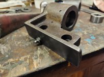
What you call the bottom tray, I think of as oil pan. And next to it the clutch lever and rod support is mounted, with two bolts from underneath. Mine removed and on bench:
124.jpg

I will still use a grease fitting, but I stamped "oil only" on face. A little hard to see, I need to blacken letters:

243.jpg

I adapted an oil can to have a grease gun coupling. I can shoot oil into grease fittings where appropriate, and not worry about chips getting in the hole:
132.jpg
 
Cal - TGT noted previously in this thread - but couldn't find an image of your modification on the top of the carriage.
Do you have an image or a link to the mod you made to manually fill that reservoir?
(I'm pretty sure I've read it - not sure if it had pics tho)
Quick search didn't turn up.
 
Guys, I run about 25% automatic trans fluid in my apron, it help clean the system and prevents the plugging and dirty build up. Just pulled the saddle and the inside of the apron still looks new. Test the oil system and it is spot on!!2023-04-03 19.01.36.jpg2023-04-03 19.12.11.jpg2023-04-03 18.27.43.jpg


Back
Top