What's new
What's new

Mold base opinions

DME Master Unit Die (MUD) - DME

They actually commercially make mold bases that have interchangeable inserts. I would guess you would be fine, just pick up the same leader/bushing on each side and should be ok. Not sure on details, but the inserts should be 'proud' about .001" or so of pocket for sealing.


Is that the total stick out or can I go .0015 or so on each pocket? Overall .002 -.003
 
Hi Pressman:
I've noticed a few posters recommend leaving the inserts proud so they will seal when the press closes.
Normally with a conventional sprue and runner system originating from the center top of the mold and going through the hotside plate, I would have no objection to this strategy.

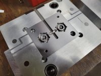
But you have stated that you are spruing and gating from the side, and the mold plates you showed in one of your earlier posts shows that clearly.

That changes everything!
If you want to avoid flashing of the runner system, you MUST seal on the mold base as well as the inserts.

Flashing of the runner system is undesirable for a couple of reasons:
First, it leaves flash and trash all over the mold base and that flash will beat the shit out of the mold very quickly:

This was drool from the sprue, not flash but the effect is the same:
Picture 004.jpg

Second, it prevents the building of injection pressure early in the injection cycle until you can plug the gap with congealed plastic, so it screws up the injection.
Third, if you make it bad enough it represents a hazard to the press operator.
Molten plastic squirting out the parting line is bad...plastic burns are particularly nasty.

So be careful with how much you leave the inserts proud on a build like this one.
Ideally everything is dead nuts flat and stays that way as the mold is cycled.

Unfortunately in real life, everything squashes and distorts...you are trying to get a sense of how much and compensate accordingly.
The clamping pressure squashes things a bit.
The injection pressure make the mold want to inflate like a balloon.
The platens are not perfectly flat and don't come together with perfect parallelism.

So don't get too carried away making the inserts proud on a side sprued mold.
0.001" per side is the maximum I'd consider, and only if I have no way of making the finish and flatness on the pocket floors nice, and only if I don't have a surface grinder to make the inserts properly flat.
You will be left with a 0.002" gap...OK if you shoot polycarbonate but not OK if you shoot nylon.

Normally with a grinder and a way of making good pockets, I'd aim for a perfect match (or maybe 0.0002" proud), and typically, if the mold couldn't be made to seal I'd make the jacks proud a thou or so to bend the B plate a bit, and if it was bad, or the press was crappy or the mold was huge, I'd crown the top and bottom plates a twitch.

Note this is most true for the side sprued mold...a conventionally sprued mold with a center sprue bushing is far more forgiving so long as everything along the flow path is contained within the inserts.

Cheers

Marcus
Implant Mechanix • Design & Innovation > HOME
Vancouver Wire EDM -- Wire EDM Machining
 
RE: Pocket corners.

I normally programed the inside corners of pockets .005" greater than the tool radius that was cutting the pocket, ie. .380" for a 3/4" end mill. I would then round the corners of the inserts true radius, but about .005" in from true position, leaving .005" grind stock on each side of the insert before heat treatment. When fitting to the pocket, this normally left scant clearance in the corners, so no fitting required on the corner radii, and minimum gap at the corners that was not likely to hold any trash. I did keep old, small grinding wheels dressed to .250" R and .375" R in case the above didn't work out.

Dennis
 
Interesting Dennis:
I used to do pretty much the same thing, but I'd program all the pocket corners to be a non-standard radius enough bigger than my cutter so I could interpolate around the corner instead of slamming into it.

I'd then program an 0.005" smaller radius at the same center location with a radiused lead in and lead out on my insert corners so I'd nominally have a 0.005" gap at the corners, and I could grind in the inserts without hitting those corner rads.
This allowed me to ditch those Godawful corner rounding cutters...you know...the ones that graunch and grind and leave a shitty finish like a rat's been chewing on it.

Sounds like you do much the same.

Cheers
Marcus
Implant Mechanix • Design & Innovation > HOME
Vancouver Wire EDM -- Wire EDM Machining
 
RE: Inserts proud of cavity plate on P/L injection mold.

Since the gentleman is putting tool steel inserts in an aluminum mold base in a P/L injection application, I think I'd cut some rectangular pockets out to the edge of the plates for tool steel inserts for the runner. These would be the same height as the cavity inserts, and have the added advantage to provide a hard steel surface for the nozzle to bear against.

Dennis

I thought about this too. Re- cutting my sprue bushing pocket and adding tool steel down to the insert. I might go this route if this doesn't work as I hope. I'm currently sitting about .0002-.0005 proud on each side of the mold base now. It's a really simple part I'm making so this should be sufficient.

On a side note. I'm looking at a Battenfeld 350plus so I may be getting away from part line molds!
 
Just about done with my very first attempt at making a mold. Very tedious work but super fun.

Trying to figure out how many and where to put my vent marks on the insert. Any suggestions? Thanks!!

20220329_082221.jpg
 
Hi Pressman:
Looks pretty darn nice!
I'd vent these with a semicircular vent of about 0.0005" that occupies a third to a half of the circumference of each cavity directly opposite the gate.
I'd make the vent land about 1/16" per side bigger than the biggest dimension of the cavity and then make a ditch about 0.005" to 0.010" deep with a ball cutter so it's easy to wipe clean.
I'd run a channel out to the edges of the mold or just use the channels that are already there.

You want the vent to be opposite the gate so the air can whoosh out even as the last bit of the cavity at the parting line fills with plastic.
How much of the circumference you vent is a personal guess...you'll do no harm venting all the way around the cavity, but it will likely work even if you go only a quarter of the circumference.

Cheers

Marcus
Implant Mechanix • Design & Innovation > HOME
Vancouver Wire EDM -- Wire EDM Machining
 
Just about done with my very first attempt at making a mold. Very tedious work but super fun.

Trying to figure out how many and where to put my vent marks on the insert. Any suggestions? Thanks!!

View attachment 345810
All our molds get a peripheral vent around the entire part, with the exception of watching out for the runner with the dump of course. And speaking of runner, that's one of the most important things to vent, out the ends of the runners. I would vent that center core pin as well!
 
I have a different take on this.

First off, nice cavity work. However, I don't see any ejector pins. If the tapered posts are also the ejector pins, the tool can't be run on automatic, the parts will tend to stick on the tapers and be drawn back into the cavities just enough to occasionally stick and not drop; the press closing will tend to shave off plastic which will beat up your parting line. I normally grind these kind of features on stationary core pins and surround them with at least three ejector pins so the part comes out straight.

Don't take Marcus' recommended vent depths without checking the tech recommendations for the resin you'll be using; I don't recall you telling us what that will be. If it's Nylon that .0005" deep vent will flash for sure. I recall the recommendation for Nylon vents is mask off the vent land and bead blast it with glass beads. The rough surface is all you need.

I normally grind vents, it gives finer control on the depth. I tend to go about .200" wide on parts this size, mostly because I had a job that required that width fine wheel eons ago, and that wheel is still around. When I dress this wheel for vents, I do break the corners with a hand stone so the vent doesn't have 90* edges that might hold any flash. I set up on the grinder, and touch off on a spot of Sharpie ink in the area that will be the exhaust channel until the ink just smears, zero the down feed, and back up to grind the land to depth. I use .0005 deep by .100 wide for HIPS, then set the table stop and grind in from the edge of the insert .005 deep. That's one advantage of setting the inserts .005 - .010 above the face of the cavity plate. You will have to extend the channels out to the edges of the mold.

The vent at the end of the runner is important; it gets rid of most the air and any gas that comes out of the nozzle ahead of the melt. It can also be overly deep, within reason, because it will seal with plastic before the cavities fill and develop full pressure. Also, nobody inspects runners for quality defects.

As to the cavities, I tend to let the pins do most the work. Each ejector pin has .0003 - .0005 clearance that will vent air, this can be augmented by grinding one or more air flats on their circumference to within .100 of the cavity surface. The tapered core pins could be done this way also, and can be increased by grinding that last .100 beyond the end of the air flats to create a land that is the recommended vent depth than the hole diameter; the bulk of the pin surface between the air flats will keep it centered.

With most the air out of the cavities, that leaves the last little bit that's trapped when the melt closes off the pin vents. At this point I normally test shoot the mold, a luxury you have when you build and run your own tooling. If there is too much air trapped you will see a burn mark on the part, known as "Dieseling" because the air is reaching the ignition temperature of the plastic. Don't run it long like this, because it WILL erode the cavity wall. If this is a problem, I cut one vent where it is occurring, as this is the last place to fill.

Good luck, and again, nice work.

Dennis


Back
Top