What's new
What's new

Monarch 12CKK, Prepping to Get Back in Service

I have come to the conclusion that I will tear this lathe down, separating the large major pieces. Not a major rebuild. But a decent clean up I hope. As well as addressing some repairs along the way. Plus the electric motor looks like original, and very cool, I'd like to rehab that as well.

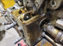
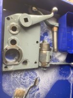
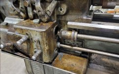
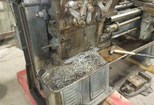
Figuring I'd start with the obvious and see what I need to fix the broken clutch assembly. To figure it out, I'd have to get at least the qcgb end plate off. As it turns out, you must remove that end plate to have any chance to remove the qcgb assembly anyhow. Leadscrew yanked out:
View attachment 392866

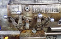
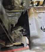
Poking around to see how I might access I was curious about going through the start/stop switch hole. To my surprise there is no switch on the other side of cover. The power switch buttons are rods going through qcgb and lathe bed.
View attachment 392867 View attachment 392868

The reason end plate must be removed is the feed rod is the shaft for feed rod gear. The gear is attached to feed rod be taper pin. The only way to access the taper pin is to un-bolt qcgb end plate, and slide end plate and feed rod together a few inches, and with gear more accessible, knock out the taper pin. With gear removed, qcgb end plate slides off feed rod.

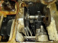
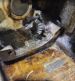
With that done, we can see into the first section of qcgb. I'm pretty sure all the chips got into this section from the key slots in the shafts going through end plate, I'm thinking I'm going to do something about that, luckily gears not damaged. We also have a better view of the power switch rods:

View attachment 392869
My 12CK had the same push rod with switch on the back side of the headstock, although On/Off (no reverse option). I ended up replacing the actual switch on the back side with low voltage momentary contact switches that feed into the VFD. I have alternate switches on a small panel, but the factory front panel still works :)
 
My 12CK had the same push rod with switch on the back side of the headstock, although On/Off (no reverse option). I ended up replacing the actual switch on the back side with low voltage momentary contact switches that feed into the VFD. I have alternate switches on a small panel, but the factory front panel still works :)
I have not taken the time to understand or test it electrically, but popping the cover on rear side of bed, the mechanism seems all there and in good order. If possible I hope to reuse it. I really like the switch cover and thread chart are in bronze.

On a different note. . . I really don't need to add projects to my projects, but I'm toying with the idea of adding a leadscrew reverse rod and the lever on apron. Currently its just a lever on headstock:
26.JPG

My end bearing already has the location for it:
25.JPG

The holes in apron are already there. Just capped off.

And qcgb has the bored through holes as well:
22.JPG

I'd need a new top cover on qcgb, or make a new one maybe. Funny enough, they even left the detent mechanism for the whole assembly, circled in red:
23.JPG
 
On a different note. . . I really don't need to add projects to my projects, but I'm toying with the idea of adding a leadscrew reverse rod and the lever on apron. Currently its just a lever on headstock:
Interesting that the CKK has the motor reverse but not the apron leadscrew reverse, where the CK has the apron leadscrew reverse but not the motor reverse.
 
Interesting that the CKK has the motor reverse but not the apron leadscrew reverse, where the CK has the apron leadscrew reverse but not the motor reverse.
If you have time, and its not too much trouble, if you could lift the lid on yours I'd love to see a pic of the mechanisms involved. I've bought what manuals were available, but the layout of parts pics are not the type you can decipher location and order. I've seen the pic of your style with the humped lid, just not what's inside.

On the series 61 a worm gear is basically an extension of the rod through apron. What the worm gear moves ultimately spins a set of beveled gears to make the 90 degree turn into head stock (don't mind the red circles) worm gear seen at top of qcgb in the middle:
337.jpg

The location of detent mechanism to hold fwd/neu/rev is from above on a series 60, seen right side in pic:
9.jpg

And again, we see detent below on the 12 ckk:
23.JPG
 
Last edited:
If you have time, and its not too much trouble, if you could lift the lid on yours I'd love to see a pic of the mechanisms involved. I've bought what manuals were available, but the layout of parts pics are not the type you can decipher location and order. I've seen the pic of your style with the humped lid, just not what's inside.

On the series 61 a worm gear is basically an extension of the rod through apron. What the worm gear moves ultimately spins a set of beveled gears to make the 90 degree turn into head stock (don't mind the red circles) worm gear seen at top of qcgb in the middle:


The detent mechanism to hold fwd/neu/rev is above on a series 60, seen right side in pic:


And again, we see detent below on the 12 ckk:
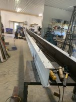
I've been in and out of the hospital the last month so I'm moving pretty slowly. Keeping up with the spring chores on the farm is leaving me less shop time than I like but I'll try to get some pics. What time I have in the shop I really need to get the bridge crane rails up, as the two 40' beams sitting up at working height for fab as rails are pretty much obstructing most anything else. In the mean time here's some pictures from my archive, I keep a few pictures from when I worked on it.
Face plate (upside down).
IMG_3019.JPG

End of the reversing rod. You can see the hole in the side of the QCGB where it goes in.
IMG_3020.JPG
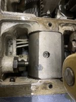
Here's the QCGB with the top off. The relevant part is the set screw and lock nut at the bottom left of the picture.
IMG_3021.JPG

IIRC, The rod has a worm gear that fits as a sleeve over the rod, behind the rack teeth cut into it. The set screw engages in the worm, so rotating the rod results in left/right motion of the rod. Or the apron hitting stops (collars) on the rod can directly move the rod left/right. The reverse selector shaft sticking out of the front of headstock has a partial gear that engages in that rack.
 
Last edited:
Quit chasing nurses you fiend, and maybe you won't be moving so slow ! Those poor ladies need to work :D. Hope all is well.
Those pics help a lot. It appears a longer shaft coming out of head stock, and I would presume one 90 degree turn to that worm gear. Where the series 61 has two 90 degree turns and a shorter shaft going into headstock.

It appears I have set screw and lock nut:
17.JPG 23.JPG
 
and I would presume one 90 degree turn to that worm gear.
Here you go:
Note the rod when turned to the left stop will extend out the left side of the raised part of the QCGB.
IMG_4996.JPG
IMG_4997.JPG

Here's that worm gear. It's threaded on the inside, with a mating threaded sleeve on the shaft. The set screw in the flat part is actually a pin on the inner sleeve through the rod, you have to get the rod turned correctly to line it all up and remove it so you can slide the rod out of the assembly.IIRC it is something of a very course thread, so that 90 degrees of rotation gives around 1" of left/right movement. Don't remember if it is square or acme (not triangular). The pin with the locknut keeps the outer sleeve from rotating.

The spring stud you have sticking up is behind the circular rack, and mates to a plate with 3 detents to provide positive engagement in the right positions.
IMG_5003.JPG
IMG_5004.JPG

For kicks, here's the rails running down the center of the shop.
IMG_4995.JPG

P.S. The problem with chasing nurses is what to do when you catch one. I'm probably doing something wrong ...
 
Last edited:
Looking at your gear chart, I'd guess your CKK is a 4 pole/1800 rpm motor?
Love the pics, sure do appreciate it. It helped confirm some things for me.

My wife's a nurse. Plus side is she's not too shy about anything. Down side, from now till the end of my days I will have pills shoved in my face and hear how my very existence is bad for my health :D.

Upon initial once over, I checked motor from front side of lathe, no tag there. Thanks to your question I pulled the rear side and found a pristine brass/bronze data tag, says 1735rpm:
32.PNG

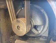
I've got a thing for old motors. Pity they need to be hidden most of the time. But when I saw this one I was pretty sure it was original, and I look forward to servicing it and making it pretty. Kind of an art deco style to it:
33.PNG 34.PNG

There's a 14 year, ongoing thread on old motors that is quite pleasant if you like that sort of thing. When I get this motor sorted out I'd probably add this to it:
Old Electric Motors
 
That looks like the motor on my 60 except smaller so it is original. I was intending to replace it with a new TENV Marathon Black Max but I put a temporary vfd on it to test and it runs so smooth that I will leave it on the machine. The 10 hp frame is a 326 so your frame is even larger in comparison to HP. Dave
 
Love the pics, sure do appreciate it. It helped confirm some things for me.
Glad to help. I like seeing these old lathes getting treated well.
My wife's a nurse. Plus side is she's not too shy about anything. Down side, from now till the end of my days I will have pills shoved in my face and hear how my very existence is bad for my health :D.
Nurses can be a lot of fun. ;)

Upon initial once over, I checked motor from front side of lathe, no tag there. Thanks to your question I pulled the rear side and found a pristine brass/bronze data tag, says 1735rpm:
I'm guessing that the headstock and gearing are interchangeable between the CK and CKK. Mine was originally a 1200 RPM motor, 3HP. That was before I had an RPC, so I used a VFD and a vector motor, but I still have the original from '44. Just haven't found something interesting to do with it, at least not yet.
 

Attachments

  • IMG_2687.jpg
    IMG_2687.jpg
    54.4 KB · Views: 9
Browsing through this thread again...
I've had my 12CK for 2 years now and really enjoy using the old thing.
The feel of it, the grunt it has, the sounds it makes, the features it has - even if I don't use them all.
Big easy to read dials, nice manly handles. It really was a machine that was built by and for machinists.
I used it more in the last couple of months than ever before.
One thing I love about it the most is the quick release tail stock. It is just a joy to use compared to tightening it down with a wrench.
One thing I havent gotten used to is the spindle speed levers. I still have to look at the chart and select the one I want.
I do have a bit of a rattle in the clutch that I need to attend to. Now that it's warming up.
I rode this old horse when it was pretty cold this winter. I bundled up and worked it in temps down to 25 degrees. Did some heavy boring. Still had an oil drip in the site glass at that temp, albeit it dripped more slowly.
When I bought this lathe at an auction I had the choice between it and a 15" Leblond dual drive. I couldn't decide so I bought them both. Got them both home and sold the Leblond. I sometimes wonder if I would have liked the Leblond as well as the Monarch. Will never know - but I can't believe I could have liked it better.
 
I sometimes wonder if I would have liked the Leblond as well as the Monarch. Will never know - but I can't believe I could have liked it better.
The smartest thing you did there was to make a decision. It allowed you to focus on one.

I find that I collect tidbits for every machine I own. The machine I've had the longest amount of time has the most tidbits, ie tooling, set ups etc. Plus more experience operating it, which adds value in its own right. You build that comfort and reliability.

No doubt you made the right choice.
 
Working to get the qcgb off. There are 4 bolts that hold it on. Plus the beveled gear for the clutch shaft through bed. And a couple of gears removed from left end of lathe.

Two of the bolts are on right side, an upper and lower. The upper here:
27.JPG

The lower is next to the beveled gear. There is a taper pin through the gear and shaft, large end of taper pin facing us. To roll 180 degrees, you'll need to remove one of the linkages for clutch at rear side of lathe:
28.JPG 29.JPG

Now if the beveled gear gear has some wear on teeth, I will spin it 180 degrees and run a reamer through taper pin hole for a new taper pin. Or we could leave the gear pinned to shaft, but rotate the other end and repin it. The reason is, the clutch arm does not make the bevel gear spin 360. It actually only uses a few teeth, maybe within 45 degrees, as you snap clutch arm down and up. If you choose to repin the other end of shaft to begin using unused portion of gear teeth, you could repin here:

30.JPG

part 1 of 2.
 
Part 2 of 2:

The other two bolts for qcgb pass through bed, and screw into qcgb. Access from gear end, of left side. In this case, I already removed two gears from the backlash adjust bracket. Note that bracket has an eye that loops around a shaft in qcgb. So it will be coming off with qcgb. The one shaft/stud is screwed into the bed, and does not want to spin out.
31.JPG

Because that stud won't come out, I slid qcgb toward left end to clear the stud:
32.JPG

Looking at the other side as I'm sliding toward left. You can also see where I shoved clutch shaft into bed:
33.JPG

With the qcgb off the bed you can see the God awful mess.
34.JPG

View of the back side of qcgb as its lifted away:
35.JPG
 
What does the shaft that the bevel gear is pinned look like?
Nothing too fancy. Pretty much a straight rod that passes through both the front and rear bedways. Worst come to worst, I could replace the shaft/rod, and use gear as template to drill and ream through gear's existing holes, same for the lever on opposite side.

On this, I think I could try gear or lever 180 degrees out from taper pin holes, but choose one side or the other depending which holes come closest to being drilled center, as Rabler mentioned.

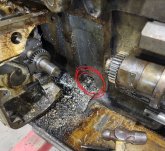
With gear removed, to remove qcgb, I pushed the rod/shaft to the rear a few inches, circled in red:
36.JPG

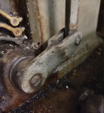
Going around to the rear of lathe, that rod/shaft is inside this clutch lever:
30.JPG

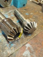
Though I may do it to this lathe, I brought it up more as an fyi. Similar design on my series 61. Due to clutch lever swing being short, you only use the same 3 or 4 gear teeth, for many many years. . . My series 61, wore gear teeth marked in yellow:
44.jpg

Simply by rotating each mating gear 180 degrees opposite of what each was, during assembly, I was able to now use brand new, unused gear teeth when setting it up:
45.jpg

On the series 61, For the one gear, I rotated shaft/rod through bed 180. That shaft was keyed on lever end, not a taper pin. I just cut a new key slot 180 out of original key slot.
 
Last edited:
I had a similar problem fitting a new leadscrew to my 10EE. The taper pin hole was drilled at an angle and off center. I set up a fixture to hold the old leadscrew, indicated in a tapered reamer to align the fixture, then drilled and reamed the taper pin hole in the new leadscrew:


Back
Top