TomBoctou
Hot Rolled
- Joined
- Dec 29, 2007
- Location
- Boston, MA, USA
Any idea what the difference between a CKK and a CK is?
Follow along with the video below to see how to install our site as a web app on your home screen.
Note: This feature may not be available in some browsers.
Looks to me like the biggest difference is the CK includes the feed/leadscrew reverse shaft in the apron, which also allows for setting stops. My CK doesn't include reverse, but I suspect from looking at the build sheet that the reverse on this CKK was an option. My '44 CK was a 3HP 6 pole motor (11xx rpm) vs this CKK being a 5HP 4 pole motor (17xx rpm). But I believe that was also an option on either lathe. My CK didn't have a coolant pump, but again that may be a build option?Any idea what the difference between a CKK and a CK is?
I'm not sure anyone knows exactly.Any idea what the difference between a CKK and a CK is?
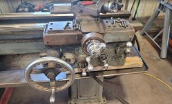
Do you by chance have some detail pictures of the taper attachment cover? The ones on my 14C are missing and I hold zero chance of finding them I'm guessing, so will try and fab some up. I'm hoping to get them as close to the originals as possible. I assume all the measurements for them between the 12 and the 14 would be different but the shape/layout is probably the same I'm guessing....Thankfully it still has the covers over taper attachment:
View attachment 384081
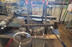
And the last pic I saved from the listing:
View attachment 384082
The main section here is one piece, with a second going over the end kinda sorta of cross slide ways. My other lathe the large piece is in two pieces:Do you by chance have some detail pictures of the taper attachment cover? The ones on my 14C are missing and I hold zero chance of finding them I'm guessing, so will try and fab some up. I'm hoping to get them as close to the originals as possible. I assume all the measurements for them between the 12 and the 14 would be different but the shape/layout is probably the same I'm guessing....

Hmmm. Do the two sides of the "tray" hinge up to access the TA? Doesn't look particularly easy to remove if not.The main section here is one piece, with a second going over the end kinda sorta of cross slide ways. My other lathe the large piece is in two pieces:
View attachment 394313
I've seen some clever adaptions the look mostly correct. Using steel baking sheets with lower edges. Cut to fit, and maybe tangs tach welded on for the screw holes.
I like the one piece cover. Slotting the bolt holes out would make removable and installation a lot easier.Hmmm. Do the two sides of the "tray" hinge up to access the TA? Doesn't look particularly easy to remove if not.
I've got the intermediary cross slide cap... just stripped all the nasty paint off it actually... is that the piece above the actual cover or is that another piece that sits on it somehow?
I think that is potentially do-able. If you have a moment when you are messing with it next time if you could take top/bottom front/back pics that would be awesome. You think it is about 18 gauge sheet?
Thanks for the help!




 [/URL]
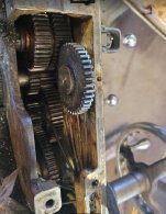
The thought crossed my mind to maybe add a chip shield of some sort as well. Not thrilled with chips so easily entering and packing that sump area and worm gear. I'll be having a better look at a solution for sure.There is a cast iron guard on ebay for a square dial 10ee for 15 bucks. Maybe it could be bolted to your 12CKK apron. It may not work without modification
There is a bar across the back. The arrow in the photo points at it. Does it reverse direction of the travel.


If the half nut is left engaged and you try to use normal carriage feed, the carriage would be trying to move. But the half nuts on the stationary leadscrew would be holding it in place even if it is disengaged at the qcgb. Something would give ....I'd have to think about the why for's and hows. Because on qcgb you select either feed rod or lead screw. One or the other spins. Anyway when half nuts are engaged you can engage cross feed, but long feed is locked out. Without feed rod spinning though, I don't think cross feed will work so. . . yeah, I need to think about that
 .
.


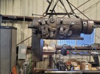

Looking back, that was one slippery slopeI have come to the conclusion that I will tear this lathe down, separating the large major pieces. Not a major rebuild. But a decent clean up I hope. As well as addressing some repairs along the way. Plus the electric motor looks like original, and very cool, I'd like to rehab that as well.
 ... My normal way of a "quick once over" too
  Great job, thanks for documenting it here.
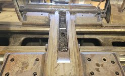
That suggests that the saddle has been milled down at some point in the past. I have the same thing on my 10EE. Look to see if the right end feed-rod/leadscrew bracket was lowered to compensate....
Looking at the oil trenches on bottom side is interesting. Not straight lines nor the lightning bolt style. Looks like it was done with a hand power tool. Not beautiful, but it was effective.
View attachment 398255
I suppose it would help, but to do it right wouldn't you have to lower the QCGB too?Look to see if the right end feed-rod/leadscrew bracket was lowered to compensate.
If you do need to take it apart, I have plenty of pictures of the one in my 12CK. The Monarch parts diagram is particularly unhelpful. I think they just included a brief picture from the clutch OEM.So I decide to leave it, before I destroyed something.

Without lowering both ends the bushing on the right would also have to be bored at a very slight angle.
Up by the headstock that method would have little effect and still put down pressure on the leadscrew and could try to raise the carriage.
I dont doubt that rebuilders may have done that but its not doing it right. I havnt pulled a gearbox so dont know what lowering it would entail but could see a possible can of worms. Maybe not?
Lower both ends or nada.
Hey! It could tighten up sloppy half nuts a little
Notice
This website or its third-party tools process personal data (e.g. browsing data or IP addresses) and use cookies or other identifiers, which are necessary for its functioning and required to achieve the purposes illustrated in the cookie policy. To learn more, please refer to the cookie policy. In case of sale of your personal information, you may opt out by sending us an email via our Contact Us page. To find out more about the categories of personal information collected and the purposes for which such information will be used, please refer to our privacy policy. You accept the use of cookies or other identifiers by closing or dismissing this notice, by scrolling this page, by clicking a link or button or by continuing to browse otherwise.
