What's new
What's new

Monarch model 61 lathe TPI/Feeds dial won't rotate.

milosav2

Plastic
Joined
Dec 14, 2022
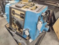
Hi all. I just purchased this monarch lathe with the dial circled in red that rotates as you turn the knob circled in green. Also, from what I've seen on youtube, the handle circled in blue has to be in the down position as well, which I have done.

The green knob does turn, but that has no effect on the dial; it does not turn. I am kind of stumped. Am i not engaging some other lever properly? Thanks much for any and all help.

The knob I have circled in green does rotate both clockwise and counterclockwise very freely; almost too easy as if it's not in contact with anything on the inside. It comes to a stop when it hits something metal on the inside. This leads me to believe that it's not engaging something properly on the inside...

[
another picture of the lathe

 
Sounds broken. "green" is connected to a cam plate and two gears that should rotate the Red after the blue is moved down.
I removed the red dial (just a flat head screw) and went to rotate the knob without the dial on the shaft and the small shaft which holds the dial twitched just a tiny amount. Could it be just a sheared pin in this shaft to the indicator dial? Do you know where I could find drawings of the interior of this machine? Thanks. Here is the shaft that comes out of the machine to which the dial is attached:

 
If you know what a regular qcgb looks or operates like, this is just a fancier and enclosed version, that's just slightly more complicated. In the end, it still has a tumbler arm that needs to slide to various positions, and raised to lock in. That lever on right side is raising and locking tumbler into position. When the lever is lowered, so is the tumbler.

Thought I had more pics. . . what is missing in my pics is a flat plate, that fits inside the opening with cover off. The plate has two gear tracks on one side. The right side lever spins the two gears visible on the front side opening. In turn, those gear make the plate slide up and down to engage the tumbler arm.

You can see the tittie sticking out of tumbler arm, its a guide to the slots above, when tumbler is engaged.

This is quite simple to investigate. Balls and springs won't go flying when you remove the front cover :D . Just removed the allen head screws from front plate, pull it off and have a look.No need to remove dial to pull the front cover.
28.jpg 59.jpg

57.jpg
 
Last edited:
Found those extra pics. Here's the interior flat plate:

353.jpg

With the flat plate tipped forward to see gear teeth:

354.jpg

I'm not finding a pic to show back side of the front cover though. It's really not all too complicated though. Pretty easy to have a look. If worse comes to worse, I can get you more pics next week.
 
Found those extra pics. Here's the interior flat plate:

View attachment 381668

With the flat plate tipped forward to see gear teeth:

View attachment 381669

I'm not finding a pic to show back side of the front cover though. It's really not all too complicated though. Pretty easy to have a look. If worse comes to worse, I can get you more pics next week.
Yup, I removed my cover and it looks exactly like that as well. Question:

This J12 gear should rotate with the larger J13 gear, right? Because otherwise if it was just floating, it would not transfer rotation to the dial, right? Well, in my case the small J12 gear rotates independently of the J13 gear.

32_53_tooth_gears.png

gears.png

Here is a video I just recorded:


If both of these gears are supposed to spin at the same time, how are they attached to the J11 gear stud? I don't see any pins, could it be just a press fit?

Parts diagram page 20 here:


Thanks.
 

Attachments

  • whatdoesthisgeardo..PNG
    whatdoesthisgeardo..PNG
    696.6 KB · Views: 6
Found those extra pics. Here's the interior flat plate:

View attachment 381668

With the flat plate tipped forward to see gear teeth:

View attachment 381669

I'm not finding a pic to show back side of the front cover though. It's really not all too complicated though. Pretty easy to have a look. If worse comes to worse, I can get you more pics next week.
Also, where to position the dial when I finally go to put everything back together?

The dial is numbered 1-11, and if we look at the tumbler plate J17 and J18 (pg 20 here: http://vintagemachinery.org/pubs/2103/18297.pdf) we can see there are 11 slots for the little arm inside to engage:


Do the slots go 1 thru 11 from right to left or from left to right?
 
I can't answer off the top of my head what pins those two gears together. But that double gear assembly, at bottom side of front cover, is the problem. Those two gears should spin as one unit, and thereby spin dial.

After you do sort it out, you'll need to clock outer dial so that it matches the correct number. This can all be done with the cover mounted back on. And its not too hard to figure out. Just roll silver dial each way the full direction, look at chart etc. With cover mounted back on, remove dial by removing the center screw from it. Roll silver knob counter clockwise to first position, and lock the lever handle up. That should be #1 on dial if I recall, but its pretty self evident when you get there.
 
Last edited:
I can't answer off the top of my head what pins those two gears together. But that double gear assembly, at bottom side of front cover, is the problem. Those two gears should spin as one unit, and thereby spin dial.

After you do sort it out, you'll need to outer clock dial so that it matches the correct number. This can all be done with the cover mounted back on. And its not too hard to figure out. Just roll silver dial each way the full direction, look at chart etc. With cover mounted back on, remove dial by removing the center screw from it. Roll silver knob counter clockwise to first position, and lock the lever handle up. That should be #1 on dial if I recall, but its pretty self evident when you get there.
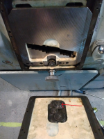
Well, the culprit was a tiny 1/16 x 1/8 pin. You can see it sheared in half:

[


Back
Top