What's new
What's new

Monarch Series 61, Rebuilding for Improvement

I had just trammed my mill, so to do all my flat surfaces first I probably should have started with the cross slide to be more efficient. But I have more meat on TS base, plus I'll be milling that deeper later on to add the bronze. So I figured I'd start with TS base in case I have any oops-ies.

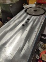
Checking the top side of TS base with a straight edge, real nice contact all over. Should be able to clamp right down to the mill table:
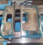
542.jpg

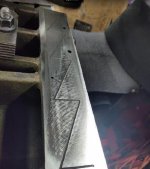
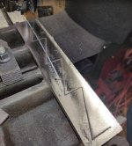
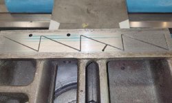
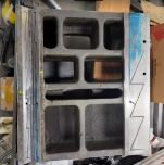
Before beginning I wanted to map out the oil passage lightning bolts. Not planning to mill past them yet, but you never know. Anyway, I'm going to need them sooner or later:

539.jpg

Getting set up for the first pass. Plan is .005" a pass, we'll see how it goes.

540.jpg

After the first pass, taking .005":

541.jpg

Taking another .005" on the 2nd pass, for a total of .010" removed. Got the majority out so far:
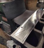
543.jpg
 
Took another .005" on third pass as well. All the wear removed from the flat way surface now, with a total of .015" removed:

544.jpg

Again, as I just trammed the mill, I didn't want to change the degrees to do vee way yet. I'll return to that once the cross slide is done.

Just messing around for shits and giggles. Thought I'd blue up bed way and see how contact looked now. Keep in mind, I didn't address the vee way yet, so sure, it wont be even. But lets have a look anyway.

While not fully across, due to vee way still uneven, real nice results. Nearly full contact on the end where flat way is contacting, and that's just from milling:

545.jpg

Not surprising, vee way contact area is a little worse. But we'll see how I do after milling it:

546.jpg

But pretty good so far, especially considering my flat way contact looked this prior to milling:

518.jpg

Another note: On TS base I was .010" low on vee way side prior to milling. Now vee way side is like .003-.004" high. I hope to come in level(ish) once vee side is milled.
 
If that person is out there, I hope they have lived every day with uncontrollable explosive diarrhea, with bouts in front of pretty girls. Besides the saddle, they like to beat on the bed at TS end as well. I'll be looking to get that out too:

View attachment 341736

My 1944 CK has the same hammer marks. Id like to think that maybe it's something to do with MFG, rather than some serial bed hammering idiot at large in the 50s (or a gang, working between Texas and Canada)

52395674591_2f819d05df_c.jpg


You have yourself a nice project. Thank-you for sharing
 
As TGT stated earlier.
Quote
I also want to machine top side of saddle's flat surfaces. Not work related, someone thought those surfaces made a good anvil

Those hammer marks and the similar marks that are often left on saddle arm flats on old lathes appear to me to be from someone using a convenient flat surface as an anvil. It's ignorant disrespect of a fine machine.
 
Last edited:
This is not a lost or forgotten project btw. There is some progress I have not posted yet, but mostly circumstances and distractions have side tracked me. This IS my number one priority project though.

In February I traveled to NY for a shipyard job that ran about a month. . .

While there I picked up another little machine. Got home and thought I'd spend a few weeks on it. . . . Then 6 months later . . . :D. Well that link is here:
Gorton 375-2 Tool Cutter Grinder

And the past few months I've taken a new job that's a few hours from my home shop. I may relocate, or not, still sorting it out. But its impacted my home shop projects.

I've started dragging my 10ee parts to my new jobs location, something to do, and to at least keep my own progress moving forward. The Series 61 being a bit too heavy to drag back and forth like a bag of groceries :D.
 
For about the past year, my weeks have been divided up between working and living at two different locations. As well as putting in a whole lot more hours than I care to think about at work. Lately, when at my regular home shop, I've been trying to make time for this Series 61 project. When away, I've try to make time for a 12CKK there.

On the 61, I've been working on two areas. One is getting the tail stock base flat and level with bed ways. The other is the the cross slide, both the top surface of cross slide, and the mating surface to carriage. For the cross slide, I began with some pics, details, and measurements on page 9, posts 177 &178.

With the cross slide being warped, I was not able to get consistent readings when attempting to use a level on it. As I eventually want to get the carriage level and true to the bed ways, I'd like to have cross slide assist in that while taking readings.

So with the cross slide warped. . .where to begin ? Hard to clamp down as it just wasn't true from either top or bottom. What I decided, was to clamp bottom side down first. Mill a few thou's off top side, flip it over mill a few thou's off bottom side. . . Gradually widdle it down close to true, While removing the least amount of material as possible. And then, be able to surface grind the top side.

Using the counter sunk bolt hole for cross feed nut to help secure cross slide to mill table. I didn't want to pull cross slide straight, only to have the warped arch spring back up when released. So laying the cross slide nature on mill table, I filled the gaps with feeler gauges and shim stock, prior to pulling it down tight with the bolt in center:
550.JPG

Due to lighting, the pic is horrible, but I got a pretty good portion of the warped arch out of top side. If I recall, taking .010" off at this point.
551.JPG

With the top side more flat, I flipped it over and was able to get the bottom side closer to true as well. With that done, I set up on my surface grinder. The cross slide on this is rather large, and it just fit in to the capacity range of the surface grinder:

552.JPG

Not perfect, if nothing else, its a whole lot prettier :D. My contact area for the level is greatly improved, though if using a level or straight edge, they will hinge somewhat near center. I'm contacting enough for consistent readings with the level now, and I have no intention of scraping to improve the hinge point. When the time comes, I will scrape the contact area for the compound though:
553.JPG

I took roughly another .005" off top side on surface grinder.
 
Last edited:
What do you think caused the warping? Seeing your, I should surface grind mine but it was flat. Dave
It seems to me that cast iron can change and even grow minutely over time, depending on a variety of circumstances. I have not studied metallurgy to give you a real good scientific answer, but I would guess stress relief over time, and force applied to it.

The cross slide is fairly long on this style. And compound rest parked at one end of it. Besides weight of the compound and tool post, the downward force of cutting tool can be pretty significant. With that, I had more wear on dial side, verse the taper attachment side.

I would guess that over the years, as that wear grew larger, the cross slide could flex more. While flexing, we probably has some stress relief. And with the stress relief, it won't be exactly the same as when initially machined.
 
While working on cross slide, I'm also working on tail stock base. The plan is still to use the TS base as the base trolley for attempting to grind carriage ways.

I'm undecided if TS ways will be ground, and I'm certain TS will be low in relation to head stock spindle. So currently, I just want the TS base to contact well, without rocking. This will not be final adjustment here.

Blueing lightly used section of bed ways, and checking TS base current contact, its pretty bad:
37.PNG

Way too much to scrape, so I'm going to mill the surfaces. The flat is easy, as I don't need perfect alignment on mill table. The vee is a bit trickier. I made a guide to go into the spindle. The guide has a close fit in the trench of vee of TS base. I then swept the table back and forth on the guide to line it up, then secured TS base to the mill table:

38.PNG

Setting the mill head at 45 degrees, I fed the knee up a couple thou's a pass until the cutter hit the entire surface. It took about .006" off each side of vee to do that:
39.PNG

From there, I spent a few hours hand scraping to get the contact area spread out. Truly horrendous chicken scratch :D, but this is not for final tail stock set up, so I was going kinda hard and fast. Up side, I did indeed get the contact surface spread out nicely, and the TS base is stable, it even slides very nice with oil.

Another win in experimenting. After milling the vee side, I ran some checks, and milled about .005" off the flat too. This got me to about half a thou from level in both directions:

42.PNG 43.PNG
 
You can shim between the base and tailstock when all squared up.
It's good to see this going forward.
My whole outlook on life gets better when I'm working on my lathe's's's
 
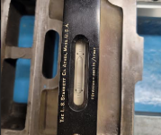
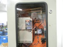
I admire your machinist skills, way above what I can do. My project this weekend was getting the VFD system installed rather than a temporary arrangement that would have given the electrical inspector a stroke. The 35.73 hz is the speed where the motor matches the speed chart with the larger pulley. Means I didn't do the math right as I thought I would be at 39 hz. Dave
 

Attachments

  • DSCN4370.JPG
    DSCN4370.JPG
    234.6 KB · Views: 22
  • DSCN4375.JPG
    DSCN4375.JPG
    221.7 KB · Views: 19
I admire your machinist skills, way above what I can do. My project this weekend was getting the VFD system installed rather than a temporary arrangement that would have given the electrical inspector a stroke. The 35.73 hz is the speed where the motor matches the speed chart with the larger pulley. Means I didn't do the math right as I thought I would be at 39 hz. Dave
Very nice. Looking good too. The green with red tags is real pleasant.
 
I painted during Christmas. Now it looks a little more like clown colors but that is for the next guy to live with. Dave

beckerkumm

Its fine, Im painting my 10ee a similar green.
Its clean and functional and looks good. Thats what is important.

OSHA came into power in the early 1970's and came into our printing company and made us paint all the adjustment handles yellow and all the belt gaurds and drive line gaurds oarnge. We had to paint yellow over chrome handles. Bugly as it gets
Safety is important but OSHA went overboard. Dictator's

TGT
When you get your sled setup ready to grind get some photos if you would.
I can't think of a better way to tackle the job. It should put everything on the same plane.
 
Harry Bloom used a sled to scrap in his 30" 10EE.
Discussion starts here: "Wreck" Update - post 65
He had a fair number of issues with the sled, so it's a good idea to look through his posts on the subject.

He decided against using the sled for grinding. There's a discussion here:
 
Harry Bloom used a sled to scrap in his 30" 10EE.
Discussion starts here: "Wreck" Update - post 65
He had a fair number of issues with the sled, so it's a good idea to look through his posts on the subject.

He decided against using the sled for grinding. There's a discussion here:
I had not seen that Hendey thread before, appreciate it. Harry using a sled in "Another new toy" thread is what got my wheels turning in this direction. Starting around page 9 of that thread, post# 172:
Another New Toy

I really wish he were around to talk to, or ask questions. A can do guy, that was quite inventive, and really did inspiring work. And successfully scraping hardened beds. . .no one does that. . .

However, I had a mental knee jerk when I really thought about trying to plane with a sled. Think about shapers and planers. They work through brute force and serious rigidity. Really think about their power and operation. . . Now Harry did things people thought impossible or way too difficult, so maybe. . . but when I think of hand cranking that sled to actually plane, its too hard for me to accept as an approach I can handle, and maybe not for other mere mortals .

In that Hendey thread you linked, he mentioned dust as a deterrent in grinding, and that he had chip and dust from planing as well. I have a few theories. One, I think his planer set up may have been throwing chips out in front of his sled. If grinding goes the way I hope, dust and debris will be directed out of the travel path of the sled.

While I don't know, and he's not around to ask. . .I have another theory too. In general I don't think he was in to grinding. In the "another new toy" thread, I noticed he sent his cross slide out to be ground, he didn't do it himself. I think lathes, mills, and such were more his strength and comfort zone. And grinding can be its own deep rabbit hole, with guys more specialized in that area. I could be wrong, just an impression from reading some of his stuff.
Attaching some tubing to the sled so it vacuums the ways right in front of the sled.
As you said the direction of the grinding wheel may make a difference.
You'll have to work through some of this as you go.
Maybe you could put a piece of teflon or something slick between the tailstock clamp and the bottom of the bed. With the taistock off you would have to use a bolt to hold the clamp.
It seems that some light hold down pressure would be good. It would have to be very consistant as it travels.
Dont know smooth the bottom clamping surface is.

This suggestion could open up a huge can of worms.

I dont guess the wheel will want to raise the sled as you travel. Your grinding setup has to be very rigid not to flex.

Your probably only going to make tiny sparks with each pass. I think with the weight of the base you may be ok.
You could add weight to the tailstock base.
Just thinking out loud. I'll shut up
IM THINKING 10EE. YOU CAN HAND CRANK YOUR SLED

With your busy scedule and two locations I suspect you will have time to think about all the possible issues.
 
Last edited:
I wonder how the problem of keeping grit off of the ways is handled by dedicated way grinding machines.

One thing that caught my eye, skimming Harry's thread, was his mention of the problem of sled teetering on the end of the bed. You would prefer that the ways for the grinder be longer than the ways being ground, else you need some way of moving the wheel to opposite ends of the sled, so that you can get to everything. I've mused about using Thomsom-style linear bearings and rods to support a way grinder.

I bet this topic has been discussed over at the reconditioning forum. They probably have some insights.


Back
Top