Kristoffer_J
Plastic
- Joined
- Apr 18, 2022
Hello!
First of all, thanks for your help and helping me out on this project. Your responses are always appreciated.
I have several questions in order to do a safe job here and do everything correctly.
Question 1:
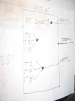
I'm having issues wiring a Techtop single phase motor. I'm not sure if I'm understanding the diagram correctly, I would like to do a double check in order to proceed with everything. The connection is for low voltage.
The cables are labeled as:
{T8 RED
{T3 ORANGE Taped together}
{P2 BLACK
[P1 BLUE (HANGING)]
{T2 WHITE
{T4 YELLOW Taped together}
{T5 BLACK
I was left with one blue cable (P1) that is literally alone.
The power cord has GREEN, WHITE and BLACK cables.
Question 2: The GREEN cable goes directly to the motor ground?
Question 3: In the on/off switch I will be left with two ends of the GREEN cable (ground) and the switch has a screw that has the ground symbol. Do I need to merge those two ends to the same ground located in the switch?
Thanks!!


