What's new
What's new

Need to bend stainless plate. This technique look ok?

David916

Aluminum
Joined
Jul 5, 2020
Need to mass produce a part made of 3/16" thick x 6" wide x 24" long 304 stainless that requires two 90 degree bends.

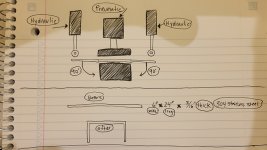
I made a quick sketch to get a rough idea of a potential layout. Was thinking about using two hydraulic cylinders to bend the two ends of the part 90 degrees downward and a pneumatic cylinder to clamp the center of the part so it doesn't warp.

Please note, I drew the cylinders way too far away from the bend line by accident. They would be moved inwards and sit right up against the bend line and the hydraulic cylinders would have metal rollers attached to the rod end to prevent marring.

The top part of the drawing is the proposed setup of the build and the bottom half is the before and after.

Am I close or way off and if so, is there a better way? I have access to every type of machinery and a fiber laser cutter and am open to building the best possible setup. Have quite a bit of brain damage from a severe accident and figuring things out is a bit hard so usually I need to build something a few times to get it right and thought I'd ask for some feedback to reduce the trial and error.

Any advice would be appreciate.

Thanks,
Dave
 

Attachments

  • 20221104_101828.jpg
    20221104_101828.jpg
    309.7 KB · Views: 86
Looks fine to me, other than bring the cylinders inboard more closer to the centre form. To get pedantic, incline the tops of the cylinders 1-2* outwards and undercut taper on the form to allow for over-bending.

Hitting a form at 90* doesn’t mean the part will have 90* walls. It’ll need over-bending of some kind, there are reference books for the taper angle or someone here may be able to give a close approximation.

How’re you gonna time the cylinders? Are we totally re-designing this? Spring pressure-pad that hits before the bends dies come down…
 
Hi RC Mech, I really appreciate your reply.

Ah! You're absolutely right, completely forgot the work piece needs to go a bit past the desired bend to get at 90 degrees and account for a tad of spring back.

Yes, this would be a brand new design. I was thinking about buying these cylinders from eBay in the attached photo.

For the bend mechanism, would you use a top plate with a hinges like in the latest sketch or a hydraulic cylinder with a metal roller? I figure the hinged system will guide the cylinder on path (might actually break the hinge?) now that the cylinder needs to be at an incline. Or, If I didn't use the pivot mount cylinder and found a cylinder that has a flange mount, I could then mount it at an incline with 4 bolts and wouldn't need a guide, like the hinge?

For the clamp mechanism, would you use a pneumatic cylinder in the middle to clamp the workpiece or a hydraulic cylinder with springs and a pad? I designed a clamp with springs and a pad a long time ago and attached the image. Might be a good idea? I wasn't sure if an assembly using a pneumatic cylinder would be easier to make and if it would work. Wondering if 120psi will be enough to prevent the workpiece from warping when the hydraulic cylinder makes the bend?

Attached is the updated sketch, am I getting closer?
 

Attachments

  • Screen Shot 2022-11-04 at 4.12.30 PM.png
    Screen Shot 2022-11-04 at 4.12.30 PM.png
    215.4 KB · Views: 24
  • Screen Shot 2022-11-04 at 4.31.03 PM.png
    Screen Shot 2022-11-04 at 4.31.03 PM.png
    108.9 KB · Views: 19
  • Screen Shot 2022-11-04 at 4.31.42 PM.png
    Screen Shot 2022-11-04 at 4.31.42 PM.png
    226.5 KB · Views: 23
  • 20221104_161933.jpg
    20221104_161933.jpg
    312.1 KB · Views: 22
What does mass produce mean?

This part would work well in a wiper type tool. You'd do the overbend by making inserts on both sides of the wiper die that engage ramps on either side of the punch. So the die does all the hard forming then the inserts just give it a little tweak to hit 90. You'd build a stripper to hold the part with spring pressure.

I would run this in a 75+ ton punch press or 100+ ton press brake. Big radius on the die. Whatever radius you want your part to have on the punch.

Very easy tool to build and can be pretty crude and still work great.
About 20pcs per day for the life of the company.

I'll look into a wiper type contraption. This is a great idea.

Also will check for 75 and 100 ton cylinders. I have a 50 ton and a 3k psi electric power pack but will gladly upgrade to have a stable system.

The radius doesn't matter. As long as the part is 90*, I'm happy.

Appreciate the advice.
 
The insert I linked is rated for 1/4" and for only 20 pcs per day you don't need to make anything. Just buy a press brake.
I build an ironworker but the problem is that I need to build a mold that can do both bends at once. I used a 30 ton cylinder but just found a 100 ton on eBay that I will buy and will build a brand more heavy duty press brake.

Do you think a 4" stroke would be enough to bend this part?

Also, how would you design the mold to bend the ends 90 degrees downward in 1 action? I attached a few photos and am wondering if I'm getting close or if there is another method. I wished you didn't show me the rotary bending die insert (kidding) because that looks so easy to use and would be perfect for this build.
 

Attachments

  • 20220322_113536.jpeg
    20220322_113536.jpeg
    108.7 KB · Views: 15
  • Screen Shot 2022-11-04 at 5.09.46 PM.png
    Screen Shot 2022-11-04 at 5.09.46 PM.png
    535.3 KB · Views: 15
I think your machine sketch is missing some parts, what geometry dictates that you need it to be in one hit and can’t use a press brake?
 
I think your machine sketch is missing some parts, what geometry dictates that you need it to be in one hit and can’t use a press brake?
Sorry, I didn't specify... If I were to use a press brake and make a jig, it would require 5 actions (insert, bend 1 end, remove, insert into the 2nd jig (one end is shorter) and bend) I'd like to bend both ends at once and make a mold that can do that. Also, it needs to be precise because sheet metal will be welded inside of it (this is a part of a machine) and a 1mm difference will fail QC.

Just noticed this and am wondering, what about a cable, winch, hinge and lever system to make the bends?
 

Attachments

  • 20221104_172235.jpg
    20221104_172235.jpg
    201 KB · Views: 15
I think your machine sketch is missing some parts, what geometry dictates that you need it to be in one hit and can’t use a press brake?
Actually, wait a second. I think you may be right. Let me draw something and I'll be back in a few...

I might be doing too much for no reason at all.
 
Okay, this is the final design. I'd make a jig wide enough to do both bends and use the press I already have and wont build another one. Very happy about that.

I know my picture is missing a few things but I drew it really fast to get the idea out of my head. The only other thing I need help with is should I make the alignment mechanism with flat bar or rods and linear flanged bearings?

The 3rd picture uses flat bar and it might be easier to build? I build a die previously (picture 4 and 5) with rods and linear bearings but the rods were very hard to align when welding because they wanted to warp.
 

Attachments

  • 20221104_174447.jpg
    20221104_174447.jpg
    253 KB · Views: 23
  • 20221104_180045 (1).jpg
    20221104_180045 (1).jpg
    226.6 KB · Views: 24
  • hydro.jpg
    hydro.jpg
    43 KB · Views: 23
  • 20220608_142327.jpeg
    20220608_142327.jpeg
    276.7 KB · Views: 23
  • 20201108_164123.jpeg
    20201108_164123.jpeg
    90.6 KB · Views: 23
Aw man, bending 3/6" 304 stainless is tough and I'm worried since the 2 jigs aren't center with the hydraulic cylinder that it will put too much strain on the sides of the cylinder and ruin the seals? Should I just have 1 insertion point with an adjustable stopper?
 
bending stainless is almost the same as a36. your spring back will be different, in a semi-closed die like the rotarys it will be about 1.3 -1.5 degrees over. Of course this is guessing and grain direction and wind speed do have some influence on this. The tighter the radius the more umph you need, and the less forgiving your tolerances in travel and dies become.
The rotary set up is the correct answer.
 
For 20 pieces a day? You need a press brake to run the rotary, just get one with a cnc back gauge and forget the rotary. That makes it what, a 10 minute job per day? Or go old school and set two fixed stops, one for each end.
 
bending stainless is almost the same as a36. your spring back will be different, in a semi-closed die like the rotarys it will be about 1.3 -1.5 degrees over. Of course this is guessing and grain direction and wind speed do have some influence on this. The tighter the radius the more umph you need, and the less forgiving your tolerances in travel and dies become.
The rotary set up is the correct answer.
I appreciate the rotary setup the most and will give them a call on Monday and ask about 4.7mm stainless. They say the max thickness is 7.5 (I'm assuming mild steel) so I'm guessing I should be ok.

Appreciate your advice.

Also, "windspeed" ? lol
 
For 20 pieces a day? You need a press brake to run the rotary, just get one with a cnc back gauge and forget the rotary. That makes it what, a 10 minute job per day? Or go old school and set two fixed stops, one for each end.
I know, 20pcs is not a lot. I have a homemade press brake with a 30 ton cylinder in the middle. I used the side bender that has a 20 ton cylinder to do the bends and it works perfect so the 30 ton should be more than enough. I just wanted to streamline the process and have 1 mold to do both bends at the same time..

Still wondering which is the best approach. I want to limit mistakes and have precise and repeatable bends.
 

Attachments

  • 20220322_113536.jpeg
    20220322_113536.jpeg
    108.7 KB · Views: 22
  • 20211225_143508.jpg
    20211225_143508.jpg
    212.4 KB · Views: 22


Back
Top