What's new
What's new

New to me Van Norman 26

Those bearings are also likely open, perhaps just remove the lower cap and flush them, see how they run. The splined shaft isn’t turning very fast and is captive within the knee, so even if there is some wear and play in the bearings as long as the helical bevel gears mesh well you’re probably ok…
 
Yes the shaft has an internal thread and if I push the shaft down in the hole and rotate it engages the thread of the bottom bolt.

The gear has about 1/8'' of radial play and 1/4" of axial play as it is. I will try to get that puller built tomorrow and see if I have any luck prying that assembly out
 
Yes, I found it very helpful to compare parts diagrams for various 2X/3X machines. Because the drawings are pre-CAD (obviously hand drawn) they sometimes got "creative" with parts placement or even left some minor parts off entirely that showed up on both earlier and later diagrams. For example, that 7366 might come from a significant distance to where the drawing implies it goes.
 
I assumed they would be different because of the knee mounted motor on 28/38 but I guess earlier they had a similar configuration to 26/36.
Part number 3-200 and 7366 are common between both drawing but clearly I don't have screw 7366 on my machine. Probably something that got added later.
1677807200516.png
1677807214843.png
 
Looking at your latest picture here, it may be useful to dig out the lead around the bearing housing you’re trying to remove.

I can’t tell if the channel the way around is clear on yours yet?

On mine the rim was probably 1/4” tall?

1677845024740.jpeg
 
I got it out!

A drilled a bunch of lead out and started chiseling what remained and then things started to move. It seems like there was an intermediate plate on my machine that doesn’t appears on any drawings. Once I took it out, I could see 5 more bolts that were holding the whole thing down. I chiseled more lead and then used a makeshift puller on the ¼-20 holes. Everything came out easy.

The 1/4-20 holes were not thru holes on my assembly so usings screw to jack the whole thing wouldn’t have worked.

The bearings from the vertical shaft are angle contact bearings but the ones that were on the horizontal shaft were just regular bearing. Are these supposed to be angle contact too?
PXL_20230303_155734536.jpgPXL_20230303_163732396.jpgPXL_20230303_163736285.jpg
 
Last edited:
nice. I'll see if I have any notes about what the bearings were on the VN22L, I don't *think* the horizontal shaft had angular contacts.
 

jdbouchard60 and Brandenberger, your posts and generous photos are going to tremendously help the next guy that has to work on this part of a 26/36. Much appreciated, even if I have a different model (28A).​

 
Very thankful for the help I received here.

When I put it back together, I'm going to take more picture of the process and create a new thread with a step-by-step procedure on how to take this apart with P/N for bearings and all. I think it's going to be more useful in it's own self-contained thread like that.

I'm also going to keep documenting the rest of my adventures with this machine in the current thread.
 
I need to pick your brains for a minute.
1678121707170.png
I don’t know what to make of the screw that threads at the bottom of the splined shaft (112-823). I can now understand why it was unthreaded; it is so short that it only engages half of a thread ... It doesn’t look broken or anything, it’s weird.

On the one hand, if I decide that this screw is important I will need to build a longer one that properly engages multiple threads. Using that screw really complicates the reassembly of the whole housing thing. I think I would have to elevate the machine and put that screw back in from under the foot. The only other option is to install the press fit bushing (2L-243) last and I’m afraid that all that heat is going to damage the rubber seal that rides against it.

On the other hands I don’t really see the value added by that screw. It prevents the shaft from being pulled out the of housing. Without it, the only thing keeping the shaft down is its own weight but to me it seems enough. There isn’t any force applied vertically to this shaft in operation I think.

I’m edging toward not reusing the screw, but I would like your opinions on this.

Also, for future reference, the bearings for the vertical shaft are Hoffman 150AC Thrust bearings. I can’t find any info on the pressure angles. I’m going to replace it with a SKF 7210B which has a 40deg pressure angle and is much cheaper and available that 7210A that has a 25deg angle. From what I can understand the only difference is the max RPM. In both cases, the max RPM is well above the RPM of that shaft.

Bearings for the horizontal shaft are unbranded but from measuring them are equivalent to SKF 208.
 
A few thoughts:

- the splined shaft is only supposed to turn one way (don't recall which), would its rotation tend to tighten the screw?

- I assume the screw head OD of 112-823 is large enough to make contact with the ID of the bevel gear, i.e. the purpose of the screw is to retain the splined shaft at the bottom. It seems a bit odd that the screw engagement is so short... you can probably tell from the screw and/or the bottom of the threaded hole whether the screw was broken off in there or whether that's the full length of the original screw?

- I would think the only force pulling up on the splined shaft would be the tug of the spline from the knee's female spline when the knee goes up. Assuming that is smooth, perhaps you don't need the screw. On the other hand if it does move up and down, maybe that results in abuse to the oil/grease seal at the top, and perhaps wear to the key and shaft passing through the helical bevel gear.

I never removed 2L-243 equivalent from my 22LU, it was soldered in place and since I had access to the bottom, I could assemble everything with full access from both top and bottom. So I don't know how close a press fit that is, whether you could assemble the whole thing and drop it in from topside, with only at part to press onto the top at the end (maybe with another clever puller?)
 
-Yes, if the screw was somehow held stationary and you rotated the shaft it would tighten the screw. But the screw rides on a machined shoulder at the bottom the stub shaft which is keyed to the splined shaft. There is no relative motion between all these parts.

-There is no visible damage on either the screw or the threaded hole of the splined shaft. I will post some better pictures of how the component go together tonight.

As for 2L-243 I will have to machine a replacement part because I damaged it when I was trying to pull the housing out. Long story short; from above it looked like a solid shoulder, and I used a prybar underneath it. Since I’m going to machine a new one, I guess I could make it a light press fit that could be pressed with a puller or something similar.1678131350304.png
 
Meaning if I run a 2hp VFD on my 3hp motor, the motor is going to produce as much torque as a 2hp motor. Any thoughts on that?
I’m asking because I currently have 2 x 3hp motor that I could use for this conversion.
most likely, it just will sense over current and not run at all. if it runs, (ramping start and low load might make it possible) it will make the same power at the rated speed and load, if it can put out the extra current, but likely you will just have a lot of nuisance trips. if you really are worried about too much power, get a 3 HP VFD with a programmable current limit so you can dial it in to avoid that.
 
it seems like if you have to remake the splined cap anyway, you’d be able to put the whole assembly together including the bottom screw and then drop it in…
 
Quick update

Yesterday I put the whole thing back together. I ended up not taking many pictures because it was a two-person job. I decided to use the screw that holds the shaft down so it complicated reassembly a bit. I replaced the original screw with just a standard ½-13 bolt and a washer. The assembly protrude a little bit more but there is no rubbing against the cover so I just used it as is.

I also elected to 3D print a plastic bushing to replace the part that I broke while disassembling. The only purpose of that part is to ride against the seal and also prevent chips from reaching the seal. I will use PETg because of its good chemical resistance and once installed I will seal the bushing-splined shaft interface with gasket maker just to be sure.

For some reason I can't post pictures today, here is a link instead

https://photos.app.goo.gl/aBdePouFnvLZWoxf9

Here is a quick step by step of how I put it back together. This only works because I have a slide fit bushing that I can put after the fact.

1 Slide the splined shaft back in the knee and hold it high. Make sure the drive key is installed on the shaft.

2 Slide the cover on the splined shaft.

3 Slide the gear and housing assembly on the shaft.

4 As you buddy holds all the pieces up in the air, tread the retaining screw on at the bottom of the splined shaft through the housing assembly.

5 while your buddy still holds everything in the air, install the bottom cover with its 6 retaining screws.

6 At this point you are ready to drop everything in the bottom casting. The rest of the install should be straight forward.

On top of that all the motors are hooked up and all the wiring is done. The machine is fully functional! I will post a more detail post about the electrical side of things later today.
 
Here is a quick overview of what I did on the electrical side of thing.

I ended up buying a used 2hp motor for the power feed instead of using my second 3hp. The price difference between the 2 and 3 hp drive was equivalent to the price of a used the 2hp motor, so I decided to go that route and keep my second 3hp for other project

I stripped all the old electrical component, and both drives now live in the electrical box. I rigged a hand box with switches for both motor and the coolant pump + potentiometers for the motors. Most of the time they will be running full speed, but I figured it could come handy to have the ability to lower feed speed or RPM in the middle of a pass for fine tuning. It is mounted on magnets right now because I still don’t know where I want to put it.

The wife also took it upon herself to remove all the old paint with a needle scaler and applied a first coat of primer. This thing had like 6 different coats of paint on it …Dark green, red, light grey, grey, orange pale green and dark grey primer. We are still debating on the final color choice, but it already looks a lot cleaner.

Now that everything is rigged up I started to clean the inside of the knee with diesel. More updates to come with the surprises I’ll find in there I guess
 

Attachments

  • PXL_20230305_155459077.jpg
    PXL_20230305_155459077.jpg
    1.3 MB · Views: 17
  • PXL_20230315_122234104.jpg
    PXL_20230315_122234104.jpg
    1.2 MB · Views: 12
  • PXL_20230315_122205921.jpg
    PXL_20230315_122205921.jpg
    741.8 KB · Views: 17
  • PXL_20230315_122217991.jpg
    PXL_20230315_122217991.jpg
    1.2 MB · Views: 18
There is some bad information about VFD drives above.
If you have a machine tool with multiple motors and want
to run off one VFD, you absolutely can.
A strategy that works well, it to wire the VFD directly to the
main motor. Branch off this feed to the main motor, and feed
the switches or contactors that run the smaller motors.
Things like power feed motors or coolant pump motors.
In this way, with the main motor constantly connected to the
VFD, there is no circuit being broken. The VFD is happy.
As for the switching of the other motors, the VFD is protected
from inductinve spikes from the switch contacts by the riunning
main motor. Spikes on the line are just pee in the pool on the
line feeding the running motor.
The worry about many motors confusing the VFD is not an issue
if you use a Volts-Hertz configured VFD. If you bought the more
expensive sensorless vector VFD, you can run it in Volts-Herts
mode, as you really don't need that feature. I have sensorless
vector mode turned off on my milling machine VFD, because it
has so much torque, that it will snap a tap when rigid tapping
holding a tap in the drill chuck.
That is as simple as I can explain it. Buy a VFD to support the
total horsepower of all the motors, and buy the basic Volts-Hertz
model. If you wire the VFD output straight to the main motor, and
branch off for your switched accessory motors, you will never hurt
the VFD.

FWIW- I own a VN22LU


--Doozer
 
Since I got the machine, the rapid feed lever felt weird. Sometimes the slow feed clutch would not engage properly, even if the lever was fully bottomed out. Since I was cleaning the knee gearbox, I decided to take a look from the clutch access panel and noticed that there was some give between shaft 26-875 and lever 26-896.
2023-03-17_09-29-20.jpg
I removed the feed speed panel to gain access and sure enough there is a set screw + a lock nut on the side of the lever and both where completely loose. From the shape of the lever bushing, it looks like there is a key underneath that area. I tightened the set screw and nut and now the lever feels much more solid.
PXL_20230317_125157045.jpgPXL_20230317_125224544.jpg
Another issue I had was that the same rapid feed lever would not go down forcefully after engaging the rapid. From the instruction manual it seems like it should go down on its own. I opened the front cover of the knee and sure enough the spring was broken. Easy enough fix.
PXL_20230317_132137263.jpg
I’m about to put all of this back together and put some oil in it. In a old post a user commented on how hard it was to put the speed change mechanism back in it’s proper position and I can see why now. I’m going to try to come up with a solution to do that easily since I’m putting it back with RTV and can’t afford to put it in and out multiple times. It has go to right where it belongs on the first try. I’ll report back on that.

Side note: there are two manuals for VN26 on Vintage Machinery. One is a bad quality scan of only the part diagram, but the machine seems similar to mine. The second manual is of much better quality but is a newer style, the ram and overarm support are different.

I found this manual https://industrialmanuals.com/norman-26su-36su-milling-operations-maintenance-manual-p-5679.php and have to report that it was a well spent $19. It has all the instructions + the part list and the quality is excellent. I can print the pages on 11x17 paper and it doesn’t even look scaled up. Also, the machine in the manual looks identical to mine.
 
Here is a quick overview of what I did on the electrical side of thing.

Interesting dominant use of solid wire. The terminals
on the VFD may not be rated to accept solid wire,
even though it might fit. The solid wire can pressure
the terminal strips that are directly soldered to the
curcuit board, and any stress can break a copper trace
on the board. Check the manual for recommendations
on this.
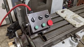
Pro tip... Hook the wire around the terminal screws
so the clockwise tightening will tighten the hook of
the bend, not try and open it. Also I see some of
the terminal screws spitting the hook out from under
the screw. Another bad condition with diminished
clamping and low conductivity.
Also, it looks like you have uninsulated ground wire
inside BX armored cable. Not typical code.
And the use of air hose as a sheath for the control
wires is "creative". The magnets on the control box
will soon reveal themselves as not the best idea.

-Doozer
 
Last edited:


Back
Top